


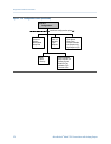
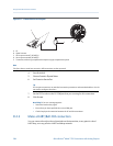
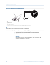
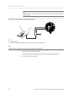
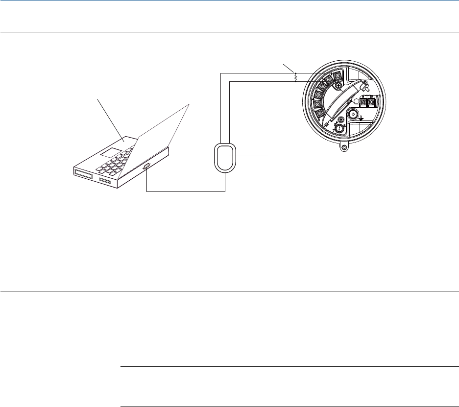
Connection to transmitter terminalsFigure D-2:
A
C
D
B
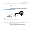
A. PC
B. Signal converter
C. 250–600
Ω
resistance
D. Transmitter, with wiring compartment and power supply compartment opened
Note
This figure shows a serial port connection. USB connections are also supported.
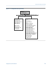
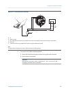
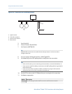
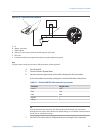
3. To connect from a point in the local HART loop:
a. Attach the leads from the signal converter to any point in the loop.
b. Add resistance as necessary.
Important
HART/Bell 202 connections require a voltage drop of 1 VDC. To achieve this, add
resistance of 250–600 Ω to the connection.
Using ProLink III with the transmitter
286 Micro Motion
®
Model 1700 Transmitters with Analog Outputs