Index
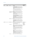
A
Added Damping 85
Additional Communications Response Delay 107
address
HART address 102, 106
Modbus address 107
air calibration, See calibration, density
alarm menu, See display
alarms
alarm codes 174
configuring alarm handling 71
Status Alarm Severity
configuring 72
options 73
transmitter response 127
troubleshooting 174
viewing and acknowledging
using ProLink II 126
using ProLink III 126
using the display 121, 124
using the Field Communicator 127
alerts, See alarms
AO Cutoff 84
Auto Scroll 62
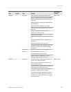
B
backups 114
basic events, See events
burst mode 104
C
Calculation Speed 70
calibration
definition 133
density D1 and D2
overview 161
using ProLink II 161
using ProLink III 163
using the Field Communicator 164
density D3 and D4
overview 166
using ProLink II 166
using ProLink III 167
using the Field Communicator 168
mA outputs, See mA outputs, trimming
temperature
using ProLink II 170
using ProLink III 171
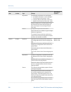
calibration parameters, See characterizing
calibration pressure, See pressure compensation
channel configuration 80
characterizing
density parameters 11
flow calibration parameters 10
parameters on sensor tags 9
procedure 8
communications, See digital communications
protocols 2
communications tools 2
configuration
backing up 114
channel 80
default values 320
density measurement 44
digital communications 102
discrete outputs 93
display 58, 64, 66
events
basic 99
enhanced 100
flowchart 17
frequency outputs 88
gas standard volume flow measurement 32
informational parameters 76
mA outputs 81
mass flow measurement 21
pressure compensation, See pressure compensation
response times 68
restore factory configuration
using ProLink II 20
using ProLink III 20
temperature measurement 49
volume flow measurement 27
write-protection 19, 115
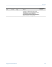
connection
Field Communicator 303
ProLink II
types 260
ProLink III
types 282
startup connection 7
Index
336 Micro Motion
®
Model 1700 Transmitters with Analog Outputs


