


b. Run the process fluid through the sensor until the sensor temperature reaches
the normal process operating temperature.
c. Stop flow through the sensor by shutting the downstream valve, and then the
upstream valve if available.
d. Verify that the sensor is blocked in, that flow has stopped, and that the sensor is
completely full of process fluid.
2. Choose Device Tools > Device Calibration > Zero Verification and Calibration > Verify Zero and
wait until the procedure completes.
3. If the zero verification procedure fails:
a. Confirm that the sensor is completely blocked in, that flow has stopped, and that
the sensor is completely full of process fluid.
b. Verify that the process fluid is not flashing or condensing, and that it does not
contain particles that can settle out.
c. Repeat the zero verification procedure.
d. If it fails again, zero the flowmeter.
For instructions on zeroing the flowmeter, see Zero the flowmeter.
Postrequisites
Restore normal flow through the sensor by opening the valves.
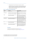
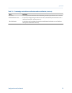
2.6.3 Terminology used with zero verification and zero
calibration
Terminology used with zero verification and zero calibrationTable 2-2:
Term Definition
Zero In general, the offset required to synchronize the left pickoff and the right pickoff under
conditions of zero flow. Unit = microseconds.
Factory Zero The zero value obtained at the factory, under laboratory conditions.
Field Zero The zero value obtained by performing a zero calibration outside the factory.
Prior Zero The zero value stored in the transmitter at the time a field zero calibration is begun. May
be the factory zero or a previous field zero.
Manual Zero The zero value stored in the transmitter, typically obtained from a zero calibration proce-
dure. It may also be configured manually. Also called “mechanical zero” or “stored zero.”
Live Zero The real-time bidirectional mass flow rate with no flow damping or mass flow cutoff ap-
plied. An adaptive damping value is applied only when the mass flow rate changes dra-
matically over a very short interval. Unit = configured mass flow measurement unit.
Zero Stability A laboratory-derived value used to calculate the expected accuracy for a sensor. Under
laboratory conditions at zero flow, the average flow rate is expected to fall within the
range defined by the Zero Stability value (0 ± Zero Stability). Each sensor size and model
has a unique Zero Stability value. Statistically, 95% of all data points should fall within the
range defined by the Zero Stability value.
Zero Calibration The procedure used to determine the zero value.
Quick start
14 Micro Motion
®
Model 1700 Transmitters with Analog Outputs