


28—UTILITY Menu Parameters
360 www.rolandus.com Roland VS-2480 Owner’s Manual
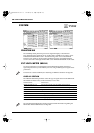
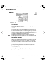
SYSTEM
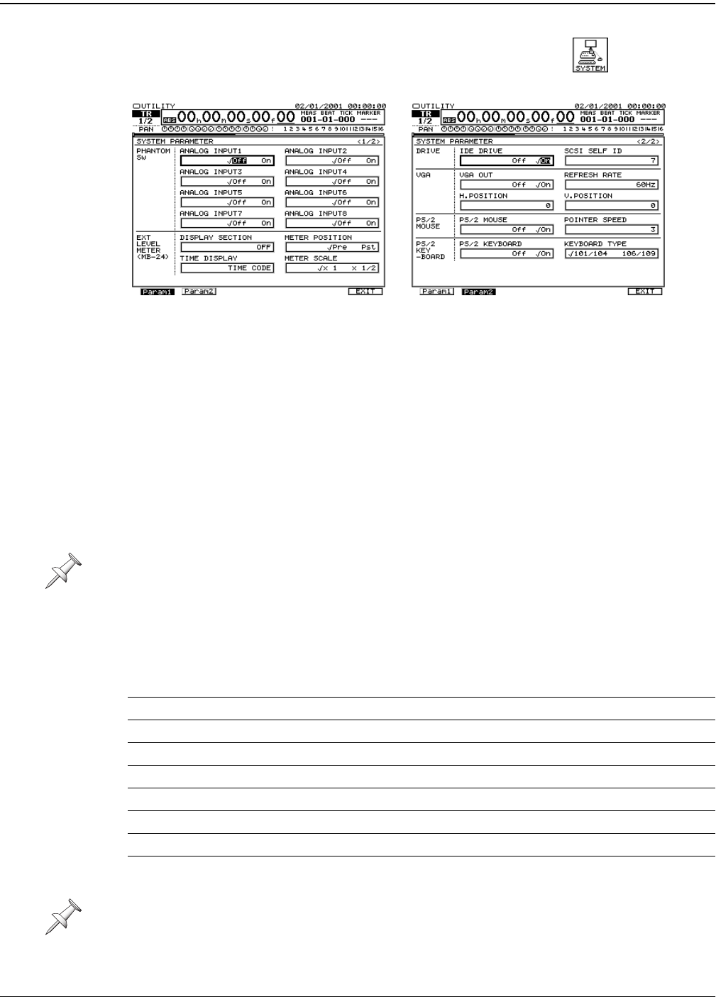
PHANTOM SW
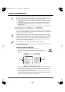
The VS-2480 provides phantom power for its eight XLR inputs, as described on
Page 130. Each input’s phantom power on/off switch is available in two places, on the
EZ ROUTING PATCH BAY screen—described on Page 130—and on the SYSTEM
Param1 screen. Setting an input’s ANALOG INPUT switch on the SYSTEM Param1
screen is the same as setting its PATCH BAY screen PHANTOM POWER on/off switch.
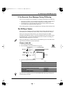
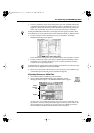
EXT LEVEL METER (MB-24)
Use these parameters to set the behavior of the MB-24 meter bridge (purchased
separately) attached to your VS-2480. If you’re not using an MB-24, you can ignore these
parameters.
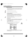
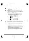
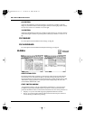
DISPLAY SECTION
The DISPLAY SECTION parameter selects the type of signals shown in the MB-24’s 24
SECTION level meters. They can be turned off, or set to show:
To learn how to attach an MB-24, see “Attaching an MB-24 Level Meter” on Page 382.
Parameter Value: Meters show:
ANALOG INPUT 1-16 the levels received at the VS-2480’s analog inputs
R-BUS/COAX/OPT IN the levels received at the R-BUS and S/P DIF digital inputs
INPUT MIXER 1-24 input channel levels
TRACK MIXER 1-24 track channel levels
FX1-8 RETURN effect processor output levels
AUX1-8/DIR1-8 Aux bus and Direct bus levels
ANALOG OUTPUT analog output jack levels
R-BUS/COAX/OPT OUT R-BUS and S/P DIF digital output levels
The “Supplemental Information” chapter provides further information regarding the
MB-24. See “Roland MB-24 Notes” on Page 396.
UTILITY menu
F1 (SYSTEM)
VS2480OMUS.book 360 ページ 2006年2月7日 火曜日 午後4時16分