


9—Working with Input Signals
Roland VS-2480 Owner’s Manual www.rolandus.com 135
Routing Input Signals to Input Channels
Much of the internal “wiring” through which a signal travels from one place to another
in the VS-2480 is virtual—the signal path is determined by your current settings, not by
permanently placed physical wires. This means that you can route signals from your 16
analog input jacks—or your 16 active digital input connectors (Page 131)—to the input
channels you want. This can save you lots of time un-plugging and re-plugging
cables—this virtual patching system lets you send a signal where you need it to go
without changing a single physical wire.
Choosing an Input Patching Screen
You can route inputs to input channels on either of two screens:
Patching
Once a signal has been routed to an input channel, you can shape the signal, add
effects to it, and send it to the desired track or tracks for recording. If you wish, you can
send it back out of the VS-2480 to some external device. See Chapter 10 for general
information on using mixer channels. Chapter 11 describes the various channel
parameters and Chapter 12 provides detailed information about using input channels.
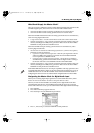
To clear all current input-to-input channel routings, press PAGE until “ClrPB” appears
above F2, and then press F2 (ClrPB). To initialize them to their default routings—with
each input connected to the corresponding input channel, and the R-BUS 1 input
connectors routed to Input Channels 17-24—press F1 (IniPB).
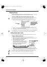
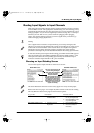
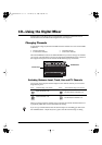
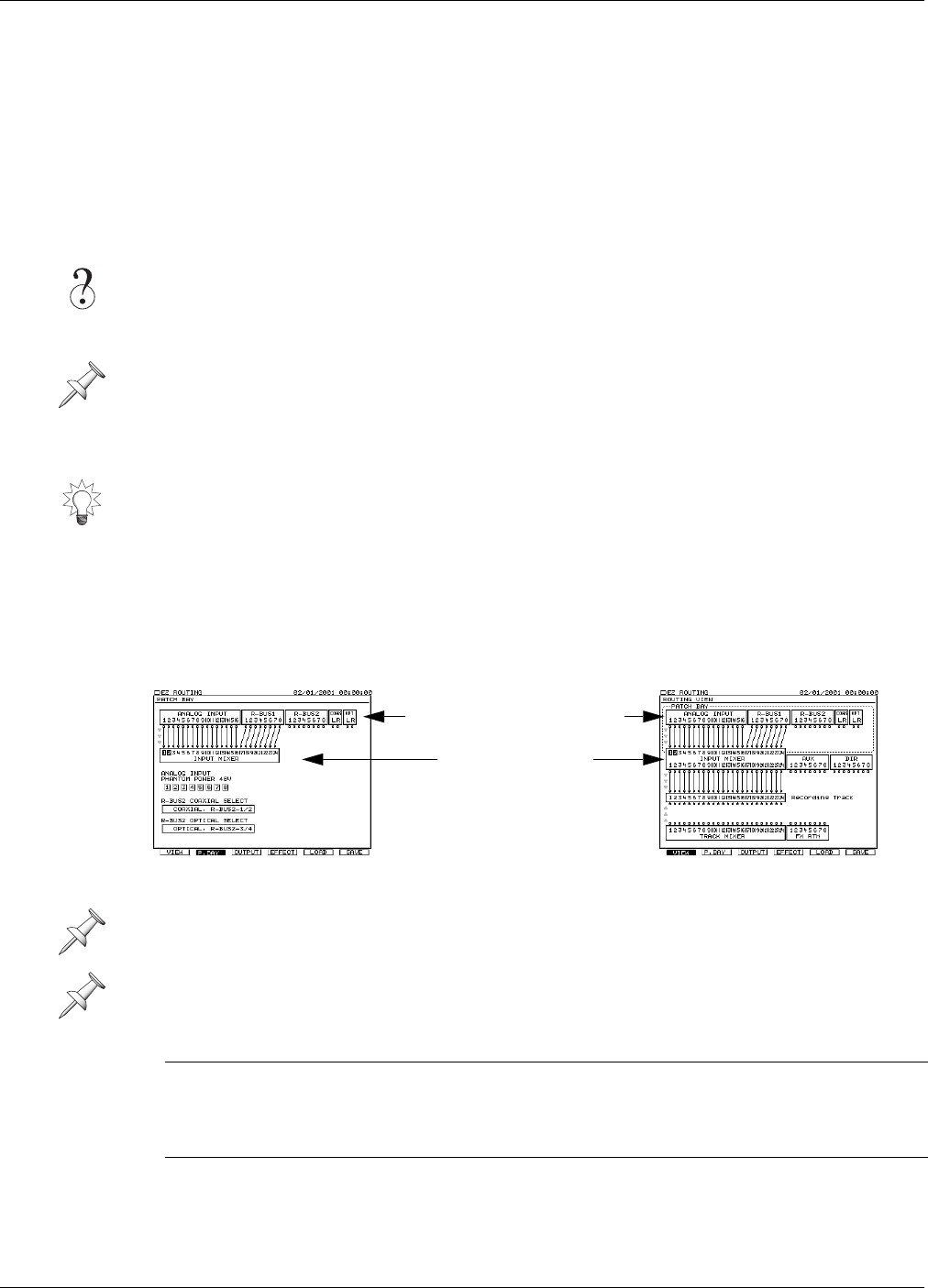
The above illustrations show the screens as they appear in a newly created project.
Both screens have two pages—see Chapter 23, either of which can be used for routing.
The only difference between the pages are their F button options.
To get to the: Fast method: Alternate method:
PATCH BAY screen 1. Hold SHIFT and press
EZ ROUTING
1. Press EZ ROUTING or
F7 on your keyboard.
2. Press F2 (P.BAY) or F2
on your keyboard
ROUTING VIEW screen 1. Press F7 on your
keyboard
1. Press EZ ROUTING.
2. Press F1 (VIEW) if
necessary
The lines between the inputs
and input channels are “wires”
that represent connections.
The light-gray arrows at the
left of each screen shows the
direction in which its wires’
signals are flowing.
This row of boxes shows all
of your analog and digital
input jacks and connectors.
This box shows the
24 input channels.
PATCH BAY screen ROUTING VIEW screen
VS2480OMUS.book 135 ページ 2006年2月7日 火曜日 午後4時16分