


23—EZ Routing
Roland VS-2480 Owner’s Manual www.rolandus.com 293
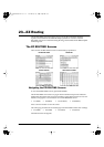
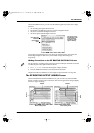
On the PATCH BAY screen, you can route the following jacks and connectors to input
channels:
• the 16 analog input jacks (XLR and 1/4”)
• The R-BUS 1 and R-BUS 2 connectors’ total of 16 digital channels
• the stereo coaxial S/P DIF digital connector
• the stereo optical S/P DIF digital connector
You can also turn phantom power on or off for the XLR input jacks, and activate the
desired digital inputs on this screen, as described on Page 130 and Page 131,
respectively.
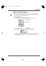
Making Connections on the EZ ROUTING PATCH BAY Screen
1. Use
,
,
or
to select the desired pair of input channels.
2. Turn the TIME/VALUE dial to create the desired connection.
Chapter 9 describes in detail how to route inputs to input channels—see Page 136.
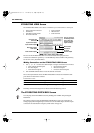
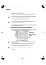
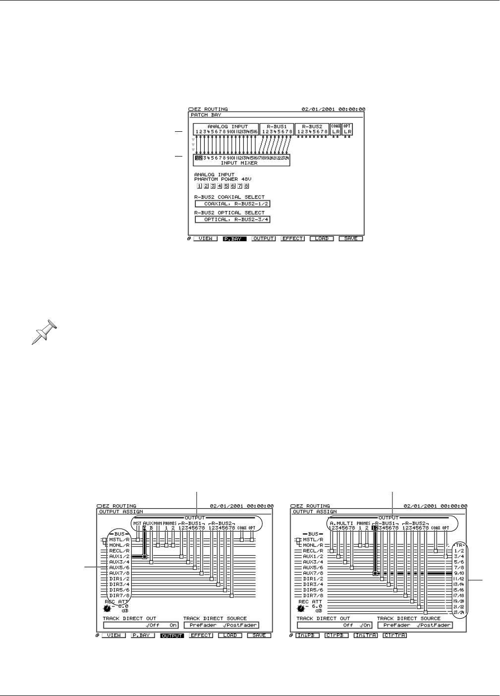
The EZ ROUTING OUTPUT ASSIGN Screen
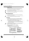
On the EZ ROUTING OUTPUT ASSIGN screen, you can route any of the VS-2480’s
busses or tracks to output jacks or connectors. The screen’s appearance changes slightly
for the two types of routing.
For the purposes of routing, input jacks and connectors and input channels are treated
as odd/even pairs. These pairs cannot be altered.
The gray arrows at
the left edge of the
screen show the
direction in which
signal is flowing.
Input channel
inputs
Input jacks and
connectors
Outputs
Busses
Outputs
Tracks
When routing busses When routing tracks
VS2480OMUS.book 293 ページ 2006年2月7日 火曜日 午後4時16分