


© 2003 Shure Incorporated DFR22 Software Guide 96
“Processor Mapping”
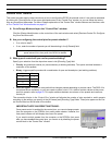
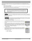
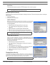
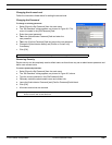
Momentary Switches
Under each momentary switch control block there are [Gain Up Limit]
and [Gain Down Limit] buttons. In addition to setting the maximum or
minimum gain of a momentary switch designated as a gain control,
these buttons allow you to set the increment in dB by which the control
raises or lowers the gain. When a gain control is pressed, it immedi-
ately raises or lowers the gain by the amount specified. If a gain control
is pressed and held, it immediately raises or lowers the gain by the
amount specified. Then, after a delay of 1000 ms, it will continue to
increment or decrement the gain every 120 ms that the control is held.
If you do not specify a gain maximum and increment for a gain up con-
trol, it will use the default values of +10 dB maximum in 2 dB steps. If
you do not specify a gain minimum and increment for a gain down con-
trol, it will use its default values of -¥ dB minimum in 2 dB steps.
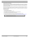
To set the gain limits for a momentary switch:
1. Click to select an input or output channel for gain up control.
2. Click the [Gain Up Limit] button.
3. The “Set Gain Maximum” dialog opens.
4. Enter the upper gain limit (maximum +10dB).
5. Enter the increment that the gain will increase each time the switch is pressed (maximum 10dB).
6. Click [OK].
7. Click to select an input or output channel for gain down control.
8. Click the [Gain Down Limit] button.
9. The “Set Gain Minimum” dialog opens.
10. Enter the lower gain limit (minimum -¥ dB).
11. Enter the increment the gain will decrease each time the switch is pressed (maximum 10dB).
12. Click [OK].
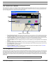
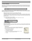
Creating a Processor Map
By assigning external hardware to the inputs and outputs you want to control, you create a processor map. You
can use one of the following methods:
• In Live Mode create a processor map for each preset in the device, one by one.
• In Design Mode open a preset file from the PC, or recall it from the device, and store a processor map with it.
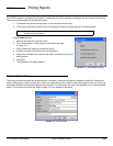
To create a processor map in Live Mode:
1. Go to Live Mode and switch to the preset you want to modify.
2. Select [Devices>Control Pin Configuration] from the main menu.
3. The “Control Pins” window opens with the input and output channels listed under the connection blocks.
4. For each connection block, click the processor mapping checkboxes next to the channels that will be con-
trolled by the hardware connection.
5. Set the gain range for any potentiometers and the gain limits and increments for any momentary switches you
are using for gain control.
6. The mapping is automatically saved with the preset in the device every time a change is made in Live Mode.
7. To set up another processor map, switch to another preset (it is not necessary to close the “Control Pins” window).
Note: You must set up a processor map for each preset in the device with which you want the hardware
controllers to function.
FIGURE 8-11: Momentary Switch
Processor Mapping