


© 2003 Shure Incorporated DFR22 Software Guide 43
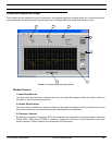
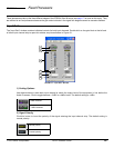
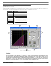
Matrix Mixer
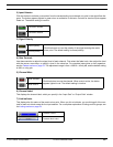
2) Input Selector
Click this button to activate a connection from the corresponding input channel mix point in the signal flow dia-
gram. The button appears lighted in green when a connection is activate. Controls for inactive inputs appear
faded out. The default setting is inactive.
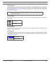
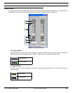
3) Signal Polarity
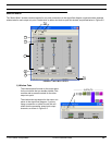
4) Gain Controls
Use these controls to adjust the signal level of each channel. First select the fader knob, then adjust the level
with the mouse, arrow keys, or specify a level in the value box. For complete instructions on their operation,
see the Faders section on page 33. The adjustment range is from +10dB to –infinity dB, and the default setting
is 0dB, or unity gain.
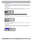
5) Channel Mute
6) Channel Label
This displays the channel label, which you specify in the “Input Gain” or “Output Gain” window.
7) Link Indicator
This displays the link status of the matrix mixer point. When you link mix blocks, you are linking all of the con-
trols for each mix block except for the input selector. For a complete explanation of linking and link groups, see
the Linking section on page 24.
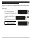
Connection activate
Connection inactive
Normal polarity
Click this button to invert the polarity of the signal entering the matrix
mixer point. The default setting is normal polarity.
Inverted polarity
Mute activated
Click this button to mute the channel. When mute is active, the button
appears lighted in red. The default setting is inactive.
Mute inactive
Processor Linked
Processor Not Linked