


© 2003 Shure Incorporated DFR22 Software Guide 20
Processor Configuration
Naming a Preset
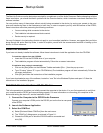
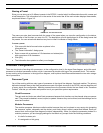
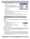
Since you can store up to 16 different presets in the DFR22, it can be helpful to differentiate them with a name and
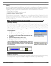
a brief description. The information box in the center of the control bar of the main window displays these details,
as pictured below in Figure 3-2.
The name you enter here becomes both the name of the preset when you store the configuration to the device,
and the name of the file when you save it to PC. The description will also be displayed in all the dialog boxes that
list presets. You can revise these details at any time in either Live Mode or Design Mode.
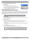
To name a preset:
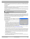
1. Click once with the left mouse button anywhere in the
information box.
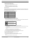
2. The “Preset Information” dialog opens.
3. Enter a name with a maximum of 15 characters and a description
with a maximum of 80 characters.
4. Click [OK]
5. The information box updates to reflect your changes.
Processor Configuration
There are two levels of working with processors: at the configuration level in the signal flow diagram, and within each
processor's individual parameter window, which is accessed by double-clicking on the processor block. This section
covers working with processors in the signal flow diagram, and explains the differences between the two main catego-
ries of processors.
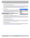
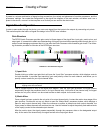
Processor Types
You will be working with two main types of processors in the signal flow diagram: fixed and modular. The primary
distinction between them is that fixed processors are part of the gain structure of the DFR22, and are therefore part
of every signal flow configuration. Modular processors are the processor blocks that are listed in the “Processor
Toolbox,” and that you can select and position to suit your particular system requirements.
Fixed Processors
The gain and mix blocks are called fixed processors because their locations on the channel strips are perma-
nent. They cannot be deleted, moved, copied, or pasted. However they can be linked, and their settings can be
saved and recalled.
Modular Processors
The modular processor blocks are called modular because they can be placed on any empty slot (excepting
the crossover, splitter, subwoofer and the ducker), and freely moved, copied, pasted and deleted. Each pro-
cessor block on the signal flow diagram functions independently. When you open the parameter window of a
modular processor, you are changing settings for that block only, except under the following conditions.
• It is half of a stereo pair.
• It is assigned to a link group.
FIGURE 3-2: The Information Box
FIGURE 3-3: “Preset Information” Dialog