


© 2003 Shure Incorporated DFR22 Software Guide 87
SECTION 8 Control Pins
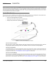
The pin connector on the rear panel of the DFR22 Audio Processor allows the installer to connect custom external hard-
ware such as switches and potentiometers for volume adjustment, channel muting, and preset selection. It can also be
used for interfacing with Crestron or AMX logic control cards. This type of simple control provides end users with a means
to control specific functions without a computer.
Control Pins Overview
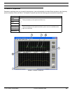
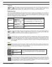
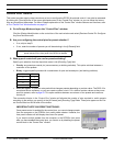
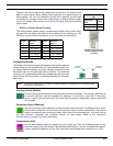
External device control is established at three different levels: external connections, pin configuration, and processor map-
ping. In the illustration below, the device is configured for the following external control:
• One-to-one switching between two presets.
• Adjusting overall system output gain with a potentiometer.
• Muting an input channel with a latching switch.
Level One: External Connections
When the device is initially installed, determine what type of external control the sound system calls for, and wire
the appropriate hardware accordingly. Refer to the Installation Guide for instructions and wiring diagrams.
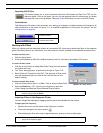
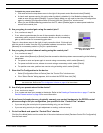
Level Two: Pin Configuration
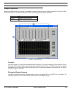
In the DFR22 software, use the “Pin Configuration” section of the “Control Pins” window to select the hardware that
is connected to the device. This configuration is stored as a global setting in the device, and can also be saved as
a computer file. Refer to the “Pin Configuration” section on page 91 for instructions.
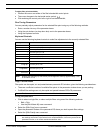
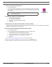
Level Three: Processor Mapping
Once the device is configured to recognize external control hardware, assign input and output channels to the con-
trol connections. Use the “Processor Mapping” section of the “Control Pins” window in the DFR22 software. Each
preset stores a unique processor map. Refer to the “Processor Mapping” section on page 95 for more information.
FIGURE 8-1: The Three Levels of External Device Control