


© 2003 Shure Incorporated DFR22 Software Guide 95
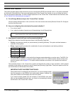
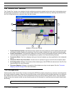
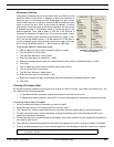
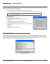
“Processor Mapping”
“Processor Mapping”
Use this section of the “Control Pins” window to specify which input and output channels the external hardware will control.
The input and output channels are listed in a column below each connection block to which a controller has been allocated.
In order for the external control hardware to control gain and channel muting, each preset in the device must be mapped to
the control connections.
Processor mapping can be created while you are in Live Mode or Design Mode. When you are in Live Mode the title bar of
this section of the window is blue, in Design Mode it is black. In Live Mode, any changes you make to processor mapping is
directly saved and applied to the current live preset.
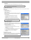
Mapping Hardware Controls to Input and Output Channels
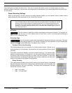
You can map any combination of input and output channels to a controller. For momentary switches, there are
three possible functions to map for each channel: gain up, gain down, and mute. Each input or output channel can
be mapped to only one of these three functions at a time. For example, you cannot set the same channel to both
gain up and to mute.
To map an input or output channel to a controller:
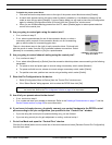
• Click a checkbox to map the corresponding input or output channel to a control.
• To de-select the checkbox, click on it again.
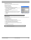
Gain Control Settings
In addition to mapping the input and output channels to gain control, you must also specify the allowable range
within which the end user can adjust the gain. As this is part of the processor mapping, these settings are saved
with each preset individually.
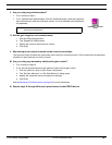
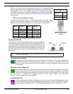
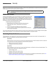
Potentiometers
Under each potentiometer control block there is a [Set Gain Range] button. If
you do not specify a gain range for each control, it defaults to -¥ dB to +10 dB.
To set the gain range of a potentiometer:
1. Click the [Set Gain Range] button.
2. The “Range Edit” dialog opens.
3. Enter the minimum and maximum allowable gain adjustment. The mini-
mum level is -¥ dB and the maximum is +10 dB.
4. Click [OK].
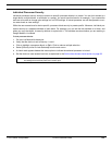
Note: Before creating a processor map, you must first create a control pin configuration and store it to
the device.
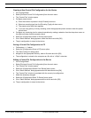
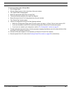
Processor checkbox selected for mapping.
Checkbox de-selected.
FIGURE 8-10: Potentiometer
Processor Mapping