


© 2003 Shure Incorporated DFR22 Software Guide 25
Processor Configuration
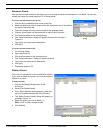
To add blocks to an existing link group:
1. Click to select a processor block, or Ctrl + Click to select multiple
blocks.
2. Select [Processor>Link>Add To] from the main menu, or
[Link>Add To] from the right-click contextual menu.
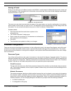
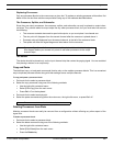
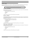
3. The “Add to Link Group” dialog appears, as shown in Figure 3-5.
It lists only the link groups that contain processors identical to the
selected block.
4. Select a link group.
5. Click [OK]
Unlinking Processor Blocks
Processor blocks can be removed from a link group without affecting other linked blocks. You can also dis-
solve a link group by unlinking all the blocks in the group.
To remove blocks from an existing link group:
1. Click to select a processor block, or Ctrl + Click to select multiple blocks.
2. Select [Processor>Link>Unlink] from the main menu, or [Link>Unlink Selected] from the right-click contex-
tual menu.
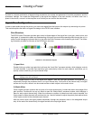
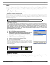
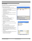
Bypassing
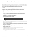
From the main window, you can bypass any modular processor block. This lets you evaluate the signal path while
temporarily excluding a processor. Bypassed blocks in the signal flow diagram display a yellow flag, as shown in
Figure 3-6.
To toggle bypass on or off:
1. Click to select a processor block, or Ctrl + Click to select multiple blocks.
2. Activate bypass with any of the following methods:
• Press Ctrl + B on the keyboard.
• Select [Processor>Bypass Selected] from the main menu.
• Select [Bypass Selected] from the right-click contextual menu.
Managing DSP Resources
Although the DFR22 has sufficient processing power for many applications, it is possible to populate the signal
flow diagram with more processor blocks than the device's DSP (digital signal processing) resources can handle.
This section explains in general terms how the Audio Processor manages the signal processing requirements of a
configuration, and gives you some hints on how to get the most out of the DSP resources.
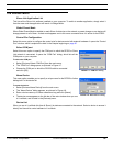
Resource Allocation
By placing a processor block on a channel strip, you are allocating the DSP resources necessary for it to run at
its maximum capacity. This is why so many varieties of the same type of processor blocks are provided; so that
you can select only the amount of processing you actually need for a given module. When you are designing a
simple configuration, it is not critical to pay attention to how much DSP is being utilized. However, the more
complicated the configuration, the more important it is to select processor blocks that use the minimal process-
ing resources necessary to get the job done.
Note: A link group must contain at least two processor blocks. Removing all but one block from a link
group will delete the group.
FIGURE 3-5: “Add to Link Group” Dialog
FIGURE 3-6: Bypassed
Processor Block