


© 2003 Shure Incorporated DFR22 Software Guide 10
The Main Window
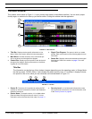
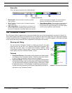
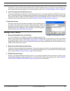
Mode Indicator
This displays the current mode of the signal flow diagram, as illustrated below.
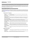
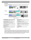
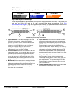
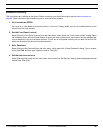
Input and Output Channel Strips
These strips are graphic representations of the input and output channels of the DFR22. They contain the
gain and mix blocks that make up the gain structure of the device, as explained in the Gain
Structure section on page 17. They also contain the slots in which you place the processor blocks, which
you can drag and drop from the “Processor Toolbox” (see page 11).
1. Input Gain Block: This is the initial stage of the Audio
Processor's gain structure. Double-clicking this block
opens the “Input Gain” window, which provides you with -
10dBV/+4dBu scaling options, channel mute, polarity con-
trol, and a +10/-infinity dB fader for each input channel.
This is also where you name your input channels.
2. Input Channel Label: This displays the channel label
that you specify in the “Input Gain” window.
3. Processor Slot: These slots are containers for the mod-
ular processor blocks. You can populate them with proces-
sors either by using the drag and drop method from the
“Processor Toolbox,” selecting the [Processor>Add] option
on the main menu, or by clicking the right mouse button
and selecting the [Add Processor] option from the contex-
tual menu.
4. Mix Points: Click on these points to route signal between
input strips and output strips. Lines appear between points
that are connected, representing the signal flow. Each input
strip may be connected to either or both output strips.
5. Channel Numbers: These numbers correspond to each
of the input and output channels.
6. Input Selectors: Click on these numbered input selec-
tors at the mix point of each output strip to instantly route
the signal from the corresponding input channel mix point.
7. Mix Block: This is the intermediate stage of the Audio
Processor's gain structure. Double-clicking this block
opens the “Matrix Mixer” window, where you can route sig-
nal from either input channel strip to either or both output
channel strips, and adjust levels with fader controls. This
window has a separate tab for each output channel strip
that displays gain, polarity, and mute controls for both input
channels.
8. Output Gain Block: Double-clicking this block opens
the “Output Gain” window, which provides you with -
10dBV/+4dBu scaling options, channel mute, polarity con-
trol, a -12dB and 18dB pad, and a +10/-infinity dB fader for
each output channel. This is the final stage of the Audio
Processor's gain structure. This is also where you name
your output channels
9. Output Channel Label: This displays the channel label
that you specify in the “Output Gain” window.
Design Mode Live Mode Preview Mode
1
2
3
4
6
7
8
9
5
FIGURE 1-4: Input and Output Channel Strips