


© 2003 Shure Incorporated DFR22 Software Guide 57
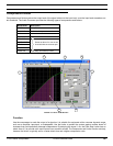
Crossover/Splitter/Subwoofer
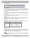
Set and Show Gains/Normalize Plot
Toggle between these two buttons to alternately display the pass bands at
their actual gain levels, and display them normalized. The default setting is
[
SET AND SHOW GAINS ON PLOT].
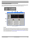
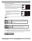
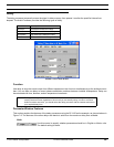
When the gain levels of pass bands are significantly different, the cross-
over point appears offset from its actual location, as illustrated in Figure 7-
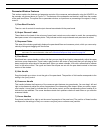
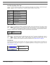
6. Use the normalize plot display mode when you need to see the precise
location of the crossover point, as illustrated in Figure 7-7.
• Click the [SET AND SHOW GAINS ON PLOT] button to display and
adjust pass band gain levels. With this setting, filter levels are
reflected in the response plotter and the gain handles are visible
on the pass bands.
• Click the [NORMALIZE PLOT] button to display the pass bands at
unity gain in the response plotter. Actual gain settings are not
affected by this setting.
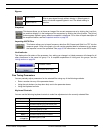
Default
Click this button to reset the processor to its system default
settings.
Mute
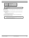
Polarity
Low Corner Freq
This indicates the frequency setting of the lower corner of the pass band. The range of values
available depends on the setting of the upper corner frequency, as corner frequencies cannot
overlap. You can change the value by clicking on the spin buttons, using the keyboard controls,
or typing in a specific value. The default values for the pass bands are listed below.
Mute active
Click this button to mute the output of its corresponding band.
When mute is active, the button appears lighted in red The default
setting is inactive.
Mute inactive
Normal polarity
Click this button to invert the polarity of the signal leaving the
crossover. The default setting is normal polarity.
Inverse polarity
Band 1
OUT
Band 2 2.0 kHz
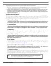
FIGURE 7-6: [SET AND SHOW GAINS
ON PLOT]
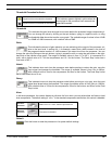
FIGURE 7-7: [NORMALIZE PLOT}