


© 2003 Shure Incorporated DFR22 Software Guide 93
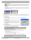
“Pin Configuration”
There is a text box for each binary setting at the control pins. The default values
begin at preset one for binary setting 0 and increment up to preset sixteen for
binary setting 1111. You can change the preset that is selected by each logic
combination by clicking in each text box and typing in a different preset number,
from one to sixteen. Refer to Appendix A: Binary Encoding Tables for the default
preset values.
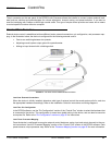
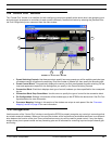
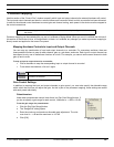
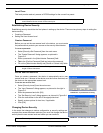
DRS10 or Custom Switch Encoding
This setting selects presets using a corresponding resistor value at the control
pin input. You can select a maximum of ten presets with this encoding type. The
DRS10 is an optional Shure accessory, or you can create a custom circuit.
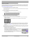
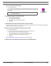
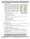
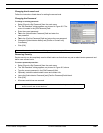
Connection Blocks
The number of connection blocks that appear in the window depends
on how many pins are available after you have specified preset con-
trol. Assign hardware controls to a pin by making a selection from the
drop-down menu on the right-hand side of the block. The hardware
control(s) can be alternately enabled and disabled by clicking on the
block with the left mouse button, or selecting [Disable] from the drop-
down menu.
Latching Switch [Switch]
Use the latching switch selection for muting input and output channels. This setting is generally for
an external controller that flips between two positions. It can also be used with a momentary
switch, in which case the channel will be muted when the switch is depressed, and unmuted when
it is released.
Momentary Switch [Moment]
Use the momentary switch setting for muting input and output channels. This setting is for an exter-
nal momentary switch that will turn muting on or off each time the switch is depressed. It can also be
used for incrementing gain up and gain down. When used for incrementing gain, you need to set up
the gain minimum, maximum, and increment amount for each preset. Refer to the Momentary
Switches section on page 96 for more information.
Potentiometer [Pot]
Use the potentiometer setting for adjusting input or output gain. Click the [Calibrate] button to cali-
brate the control input to the range of the attached potentiometer. If you do not calibrate the potenti-
ometer, the default calibration is for a 100k audio taper potentiometer with a tolerance of +/–20%.
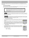
PRESET
#
RESISTOR
VALUE
PRESET
#
RESISTOR
VALUE
197 kW – ¥ W 6 7.8 – 9.3 kW
2 44 – 60 kW 7 5.2 – 6.3 kW
3 26 – 32 kW 83.3 – 4.1 kW
4 17 – 20 kW 91.9 – 2.5 kW
5 11.3 – 13.6 kW 10 0.63 – 1.1 kW
Note: If you are in Design Mode, to enable or disable the hardware connections you must store the pin
configuration to the device.
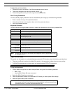
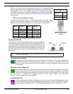
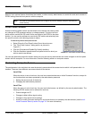
Binary Preset Encod-
ing
Max # Pre-
sets
# Pins
21
42
83
FIGURE 8-8: Preset Control
Block for DRS10/Custom
Encoding
Enabled
Connection
Disabled
Connection
FIGURE 8-9: Connection Blocks