


© 2003 Shure Incorporated DFR22 Software Guide 45
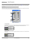
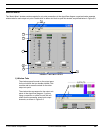
Output Gain
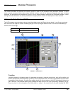
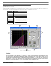
3) Gain Controls
Use these controls to adjust the signal level of each output channel. First select the fader knob, then adjust the
level with the mouse, arrow keys, or specify a level in the value box. For complete instructions on their opera-
tion, see the Faders section on page 33. The adjustment range is from +10dB to –infinity dB, and the default
setting is 0dB, or unity gain.
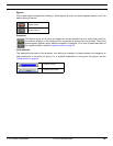
4) Output Pads
Click one of these buttons to attenuate the signal output by –12dB or –18dB. Each button appears lighted in
red when the selected pad is activated. The default status of these buttons is inactive.
5) Channel Mute
Click this button to mute the channel. When mute is active, the button appears lighted in red. The default set-
ting is inactive.
6) Channel Label
Use this text box to customize the output channel strip label in the signal flow diagram. The default setting is
“Untitled Out” for each output channel.
7) Link Indicator
This displays the link status of the output channel. Any setting you change on a linked channel will be changed
for all other channels in the same link group. For a complete explanation of linking and link groups, see the
Linking section on page 24.
12dB Pad activate
12dB Pad inactive
Note: You cannot activate the –12dB or –18dB pads simultaneously on the same output.
Mute activate
Mute inactive
Channel Linked
Channel not linked