


© 2003 Shure Incorporated DFR22 Software Guide 91
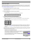
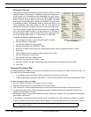
The “Control Pins” Window
The “Control Pins” Window
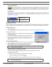
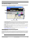
The “Control Pins” window is an interface for both configuring control pins globally at the device level, and assigning input
and output gain processors to controllers for each preset individually. Access this window by selecting the [Devices>Con-
trol Pins Configuration] menu command from the main window.
1. Preset Switching Controls: Use these controls to specify how many presets you will be switching and what type
of hardware control will perform the switching. Enter the number of presets first, then specify the encoding type.
2. Preset Control Block: This graphically displays the control pins that are allocated to preset switching. Its fea-
tures and appearance depend on the settings that you specify in the Preset Switching Controls.
3. Connection Block: Each block displays what type of control hardware you have specified for the correspond-
ing pin.
4. Connection Block Drop-Down Menu: Use this menu to specify the type of control for the connection block.
5. Pin Configuration: Settings in this section of the window apply to the DFR22 at the device level. See Pin Con-
figuration below for more information.
6. Processor Mapping: Settings in this section of the window are unique to each preset. See the “Processor
Mapping” section on page 95 for more information.
“Pin Configuration”
Use this section of the “Control Pins” window to configure the DFR22 to properly recognize any control pin connections that
are wired to external hardware. When you first open the window, all the connections are disabled and there is no differenti-
ation between the function of the pins. Once you define how many pins will be used for preset control, if any, the display
assigns those pins to preset control and any remaining pins can be allocated for controlling input and output channel gain
and muting.
Note: You must be in Design Mode to create or change the pin configuration.
1
2
3
4
5
6
FIGURE 8-5: “Control Pins” Window