


© 2003 Shure Incorporated DFR22 Software Guide 78
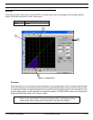
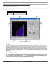
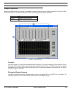
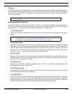
Gate/Downward Expander
Ratio
This indicates the amount of gain reduction at the processor output, relative to the input level. A
ratio of 4:1, for example, means a 1dB decrease in program level results in a 4dB decrease in
processor output level. You can change the value by clicking on the spin buttons, typing in a spe-
cific value, or using the ratio slider on the bottom edge of the transfer curve graph. The range of available val-
ues is from 1:1 to INF:1, in increments of 1/10th, with a default value of INF:1 for the gate and 4:1 for the
downward expander.
Attack
This indicates how much time the processor waits after the input signal gain exceeds the thresh-
old before returning to unity gain. The available values are from 1ms to 200ms, with a default
value of 2ms for the gate and 20ms for the downward expander.
Decay
This indicates how much time the processor takes to reach the specified gain reduction. You can
change the value by clicking on the spin buttons or typing in a specific value. The range of avail-
able values is from 50ms to 1000s, with a default value of 100ms for the gate and 50ms for the
downward expander.
Hold
This indicates how much time the processor waits after the input signal gain drops below the
threshold to begin reducing gain. You can change the value by clicking on the spin buttons or
typing in a specific value. The available range of values is from 0ms to 500ms, with a default
value of 0ms.
Default
Click this button to reset the processor to its system default settings.
Bypass
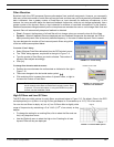
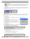
Snapshot
This feature allows you to freeze an image of the current response curve by clicking the [TAKE] but-
ton and then display it in the background for comparison by clicking the [
SHOW] button. The [SHOW]
button appears lighted in green when the snapshot is displayed. For a more in-depth description of
the snapshot feature, see the Snapshots section on page 35.
Link Indicator
This displays the link status of the processor. Any setting you change in a linked processor will change for all
other processors in the same link group. For a complete explanation of linking and link groups, see the
Linking section on page 24.
Bypass active
Click to pass signal through without altering it. When bypass
is active, the button appears lighted in red. The default set-
ting is inactive.
Bypass inactive
Processor Linked
Processor Not Linked