


© 2003 Shure Incorporated DFR22 Software Guide 58
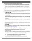
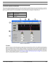
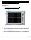
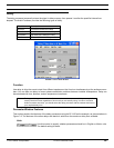
Crossover/Splitter/Subwoofer
Low Filter Type/Upper Filter Type
This indicates the slope of the corresponding pass band corner. Select a value from the pull-
down menu, as listed below. The default setting is 24dB/oct Linkwitz-Riley.
Upper Corner Freq
This indicates the frequency setting of the upper corner of the pass band. The range of values
available depends on the setting of the lower corner frequency, as corner frequencies cannot
overlap. You can change the value by clicking on the spin buttons, using the keyboard controls,
or typing in a specific value. The default values for the pass bands are listed below.
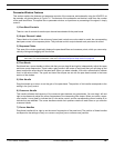
Gain
Use the gain controls to adjust the output gain levels. The range of available gain values is
between -18dB and +12dB in 0.5dB increments, with 0dB as the default value. You can
change the value using the conventions explained in the Faders section on page 33.
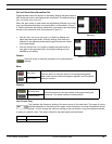
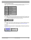
Link Indicator
This displays the link status of the processor. Any setting you change in a linked processor will change for all
other processors in the same link group. For a complete explanation of linking and link groups, see the
Linking section on page 24.
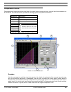
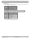
Abbreviation Description
6 Butt 6dB/oct Butterworth
6 Bessel 6dB/oct Bessel
12 Butt 12dB/oct Butterworth
12 Bess 12dB/oct Bessel
12 L-R 12dB/oct Linkwitz-Riley
18 Butt 18dB/oct Butterworth
18 Bessel 18dB/oct Bessel
24 Butt 24dB/octButterworth
24 Bess 24 dB/octBessel
24 L-R 24 dB/octLinkwitz-Riley
Band 1 2.0 kHz
Band 2
OUT
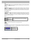
Processor Linked
Processor Not Linked