


© 2003 Shure Incorporated DFR22 Software Guide 47
Automatic Gain Control (AGC)
unchanged. The AGC only changes gain when it detects activity on its input. This prevents undesirable gain
changes during pauses in program material.
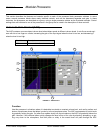
Parameter Window Features
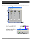
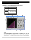
This section describes the features and parameter controls specific to the Automatic Gain Control processor, as
pictured above in Figure 7-1.
1) Maximum Gain Line
The greatest amount that the AGC will boost the signal is +12dB, as indicated by the maximum gain line. This
prevents undesirable noise modulation or acoustic feedback problems that may arise from excessively boost-
ing low-level signals. The maximum gain line only appears in the transfer curve graph when the combination of
the threshold, hinge, and ratio settings result in the AGC imposing the +12dB limit.
2) Transfer Curve Graph
The transfer curve graph displays the threshold level and compression ratio settings as graphical elements that
you can position with the mouse. The resulting transfer curve represents the change in the signal output level.
3) Threshold Slider
The position of the threshold slider corresponds to the setting in the threshold control. You can drag this slider
with the mouse, left and right along the top edge of the transfer curve graph, to change the threshold setting.
4) Ratio Slider
The position of the ratio slider corresponds to the setting in the ratio control. You can drag this slider with the
mouse, up and down along the right-hand edge of the transfer curve graph, to change the ratio setting.
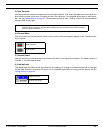
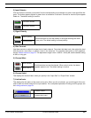
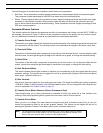
5) Gain Reduction Meter
This meter indicates the total gain boost or reduction you are achieving on the input signal with the current pro-
cessor settings. This feature can be toggled off and on by selecting the [Options>Gain Reduction Meter] menu
option. Its default status is on.
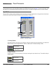
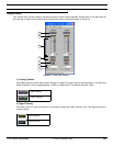
6) Gain Controls
Use the gain controls to adjust the input and output gain levels. The range of available gain values is between
-12dB and +12dB in 0.5dB increments, with 0dB as the default value. You can change the value using the con-
ventions explained in the Faders section on page 33.
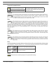
7) Hinge Slider
The position of the hinge slider corresponds to the setting in the hinge control. You can drag this slider with the
mouse, left and right along the bottom edge of the transfer curve graph, to change the hinge setting.
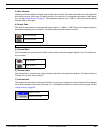
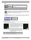
8) Transfer Curve Meter
When you are in Live Mode, this meter depicts the signal's input level and relative output level, so you can
monitor the processor's effect on the current program material. This feature can be toggled off and on by
selecting the [Options>Transfer Curve Meter] menu option. Its default status is on.
Note: You may experience reduced software performance if you have a large number of meters active over-
all in the Audio Processor software. You can selectively turn off either the transfer curve meter or the
gain reduction meter, or both, from the [Options] menu.