


© 2003 Shure Incorporated DFR22 Software Guide 14
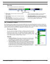
Create a Preset Template
Create a Preset Template
This can be done in either Live Mode or Design Mode. When you are storing multiple presets in the Audio Processor, you
will save considerable time by creating a preset template that contains the attributes that will be common among them. This
template can then be recalled from the device or opened from a PC, revised as necessary, then stored in the device each
time as a new preset.
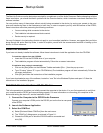
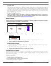
1. Select a Preset Template
When you start the DFR22 application there is a blank preset in the signal flow diagram. If you would like to use
one of the other default presets as a template, select [File>New] from the main menu and then select [Dual Mono],
[Stereo], or [Dual Mono Split]. You can also go to Live Mode and select one of the pre-loaded presets to edit. For
more information, refer to the Default Presets section on page 27.
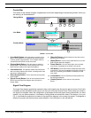
2. Name Input and Output Channels
Double-click on the input and output gain blocks to open the processor parameter windows, and edit the channel
labels that appear underneath the gain controls. For more information, refer to the Labeling Inputs and
Outputs section on page 18.
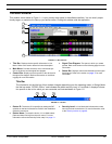
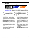
3. Populate the Signal Flow Diagram
Drag and drop signal processor blocks from the “Processor Toolbox” onto the signal flow diagram. If you are using
a crossover, it should be the first type of processor that you place in the configuration, followed by limiters, in order
to prevent loudspeaker damage. For more information, refer to the Adding Modular Processors section on
page 21.
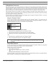
4. Create Link Groups
Ctrl + Click to select multiple processors of the same type that you would like to control as a group, for stereo
pairs, loudspeaker clusters, zones, etc. You can also link gain blocks in order to control overall system level. Select
[Processor>Link] from the main menu. For more information, refer to the Linking section on page 24.
5. Engage Pads on Outputs
You may need to engage the 12dBor 18dB pad to better align the output clipping level of the DFR22 with the input
clipping level of the equipment to which it is connected. Double-click on an output gain block to open the “Output
Gain” window and click to activate each pad as needed.
6. Route Signal From Inputs to Outputs
Click and drag from input strip connection points to output strip connection points to route the signal through the
matrix mixer. For more information, refer to the Signal Routing section on page 19.
7. Adjust Processor Settings
Double-click on each processor block to open its parameter window. If you are working off-line in Design Mode,
you can set preliminary levels and tweak them later when you are connected to the device. For more information
on working with processors, refer to the Processor Features section on page 33, as well as the reference section
for each processor.
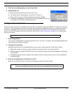
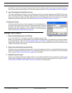
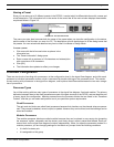
8. Map the Preset to Control Connections
This step is applicable only when you are controlling gain and/or channel muting via the control pins. Select
[Devices>Control Pin Configuration] from the main menu to open the “Control Pins” window. Select [Configura-
tion>Recall From Device] to populate the window with the current pin configuration. The input and output channels