


© 2003 Shure Incorporated DFR22 Software Guide 39
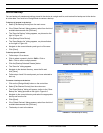
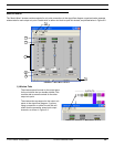
Combined Response Graph
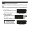
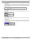
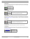
4) Snapshot
This feature allows you to freeze an image of the current combined response curve by clicking the [TAKE] but-
ton and then display it in the background for comparison by clicking the [
SHOW] button. The [SHOW] button
appears lighted in green when the snapshot is displayed. For a more in-depth description of the snapshot fea-
ture, see the Snapshots section on page 35.
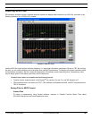
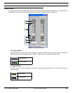
5) ASCII File Import
This feature allows you to import frequency data from SIA Smaart and Gold Line TEF into the response graph.
Once in the graph, you can use the graphical data for reference as you shape the response curve of any of the
processors in the signal path. See page 36 for instructions on how to use ASCII import.
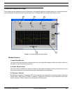
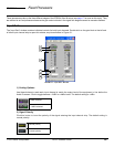
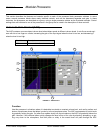
6) Response Graph
This display will update as you make changes to processor settings and processor positions in the specified
signal path.
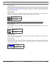
7) Polarity Indicator
The polarity displayed is for the sum total of the signal path. If an input is selected, this reflects the setting in
the Input Gain block. If an output is selected, the indicator reflects settings in the Matrix Mixer block, any cross-
over or subwoofer processor and the Output Gain block. If an input and output are both selected, all polarity
adjustments in the path are included.