


© 2003 Shure Incorporated DFR22 Software Guide 56
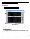
Crossover/Splitter/Subwoofer
Parameter Window Features
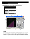
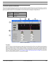
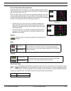
This section explains the features and parameter controls of the crossover and subwoofer using the XOVER 2 as
the example, as pictured above in Figure 7-5. The features of the subwoofer are identical, aside from the number
of the pass band filters. The splitter has no parameter window, as it performs no processing of the signal; it simply
routes it.
1) Pass Band Controls
There is a set of controls for each output channel associated with the pass bands.
2) Output Channel Labels
These labels at the head of the columns of pass band controls are color-coded to match the corresponding
band pass curves in the response plotter. They indicate to which output channel each pass band is routed.
3) Response Plotter
This area of the window graphically displays the pass band filters and crossover points, which you can manip-
ulate by clicking and dragging with the mouse.
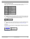
4) Pass Bands
Each band has a corner handle on either side that you can drag left and right to independently adjust the upper
and lower corner frequencies. There is also a gain handle in the center of each band that you can drag up and
down to adjust the output level of the pass band. When you select a handle, it fills with a colored ball to indicate
that it is the active control. The upper and lower filter slopes are set with the pass band controls in the lower
section of the window.
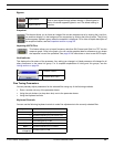
5) Gain Handle
Drag this handle up or down to set the gain of the pass band. The position of this handle corresponds to the
setting in the [
GAIN] control.
6) Crossover Handle
This handle indicates the frequency of the crossover point between two pass bands. You can drag it left and
right to simultaneously adjust the corner frequencies of the intersecting filter slopes. When you select a cross-
over handle, it turns green to indicate that it is the active control, and the corresponding corner handles fill to
indicate they are selected. The corner handles maintain their positions relative to each other as you slide the
crossover handle.
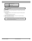
7) Corner Handles
Drag these handles left or right to set the corner frequencies of the pass band. The position of these handles
correspond to the settings in the [
LOW CORNER FREQ] and [UPPER CORNER FREQ] controls.
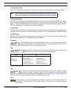
Note: To view the effect of the crossover on the signal path, select [View>Combined Response Curve] from the
main menu. For more information, refer to the Combined Response Graph section on page 38.