


© 2003 Shure Incorporated DFR22 Software Guide 40
SECTION 6 Fixed Processors
These processors make up the three different stages of the DFR22's Gain Structure (see page 17 for more on this topic). They
are referred to as fixed processors because the gain and mix blocks in the signal flow diagram cannot be moved or deleted.
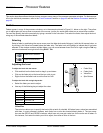
Input Gain
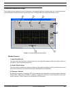
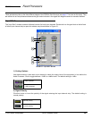
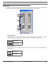
The “Input Gain” window contains individual controls for both input channels. Double-click on the gain block at the left end
of either input channel strip to open this window, as pictured below in Figure 6-1.
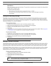
1) Scaling Options
Use these buttons to scale each input channel to match the output level of the equipment in line before the
Audio Processor. Click to toggle between -10dBV or +4dBu levels. The default setting is +4dBu.
2) Signal Polarity
Click this button to invert the polarity of the signal entering the input channel strip. The default setting is
normal polarity.
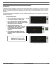
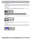
+4dBu selected
–10dBV selected
Normal polarity
Inverted polarity
1
2
3
4
5
6
FIGURE 6-1: “Input Gain” Window