


© 2003 Shure Incorporated DFR22 Software Guide 17
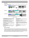
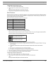
SECTION 3 Creating a Preset
A preset is a unique combination of signal routing connections, the variety and placement of modular processors, and the
processors’ settings. You create the configuration in the signal flow diagram of the main window, and either save it as a
preset in the device, or save it to the computer as a file that you can send to the device later.
Signal Flow Configuration
In order to pass audio through the device, you must route signal from the inputs to the outputs by connecting mix points.
This section explains the basics of signal flow design in the DFR22 user interface.
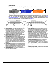
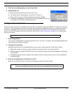
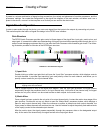
Gain Structure
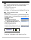
The DFR22 Audio Processor provides gain control at three stages of the signal flow: input gain, matrix mixer, and
output gain. It is essential to obtain an understanding of this gain structure before passing audio through the unit, in
order to avoid damaging equipment that is in line after the Audio Processor with excessive gain levels. The follow-
ing illustration provides an overview of the DFR22 gain structure.
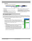
1) Input Gain
Double-clicking on either input gain block will open the “Input Gain” processor window, which displays controls
for both channels. It provides input sensitivity, gain and polarity control for each channel, and allows you to
specify custom names for your input channel strips.
This is a signal's point of entry to the signal flow diagram. After the input gain processor, the signal passes
sequentially through the processor slots on its input channel strip. At the end of the channel strip, the signal
arrives at a mix point, where it can be routed to either or both outputs via the matrix mixer.
2) Matrix Mixer
Once a signal has been routed to the mix point of an output channel strip, it enters the matrix mixer stage of the
gain structure. Double-click on any mix block to open the “Matrix Mixer” processor window, which displays a
pane for each output channel strip. When the crossover or splitter is placed over both output channels, the
mixer panes for those channels will combine into one. Use this window to adjust the polarity and relative levels
of the input(s) routed to the selected output channel.
After the matrix mixer, the signal passes sequentially through the processor slots on the designated output
strip. At the end of the channel strip, the signal arrives at the output gain block.
Note: Signal levels exceeding the input threshold of the Audio Processor must be adjusted externally to prevent
clipping at the A/D converters.
1
2
3
4
FIGURE 3-1: Gain Structure Diagram