


© 2003 Shure Incorporated DFR22 Software Guide 26
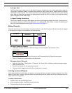
Processor Configuration
For example: when you place a ten-band parametric EQ on a channel strip, you will instantly allocate the pro-
cessing power required by all ten filters, even if you are only using four of them. The PEQ5 would be the best
choice, in this instance.
Delay Memory
The DFR22 has a memory buffer that will hold up to 10 seconds of delay time, which you can divide among
any combination of delay processors. Like DSP resources, delay memory is allocated to each processor block
according to the maximum delay time indicated in the block name.
For example, if you need 45 ms of delay, don't use the 2-second delay when the 150ms delay will do just as
well. Even though both processors may be set to the same values, the DLY 2s block still occupies a full two
seconds of delay memory.
DSP Usage Meters
These meters, located on the status bar at the bottom of the main window, indicate the amount of DSP
resources and delay memory utilized by the current configuration. Knowing the amount of DSP resources and
delay memory you have left enables you to manage your processor choices efficiently. When you add or
remove a processor block from the signal flow diagram the DSP meter instantly compiles the results, and indi-
cates the system resources that are being utilized by the current processor configuration.
DSP Optimization Hints
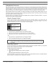
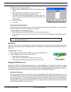
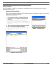
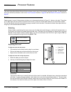
If the message box shown in Figure 3-7 appears when you attempt to
add a processor, optimize your configuration to free up DSP
resources, then add the processor. The following hints will help you
optimize DSP resources.
• Replace DFRs with parametric EQs after you are finished ringing
out the system.
For example: in a configuration where multiple DFRs are needed
on multiple inputs for better gain before feedback performance,
you could initially use a DFR on each input for ringing out the sys-
tem. After the filters are deployed, copy the DFR filters and paste
them in a PEQ, then delete the DFR. You can repeat this for the
other input, then leave only the DFRs that are necessary for auto-
matic feedback detection after the system has been configured. For more information on copying and
pasting filters between processors, see the Copy and Paste section on page 71.
• Consolidate multiple EQs on the same signal path into a single module, if possible.
Example: two PEQ3s consume more DSP than a PEQ7. Note that all PEQ's are available with cut and
shelf filters in order to conserve DSP. If you don't require the additional slope choices of the CUT/SHELF
processor, it is not necessary to include cut and shelf filters in a separate module on the same signal path.
• Consolidate multiple delays on the same signal path into a single module, if possible. Using two DLY5ms
blocks to achieve 7 ms of delay uses twice as much DSP than a single DLY150ms block, even though it
conserves Delay memory.
• Remove processors from any unused channels.
• Use the splitter to consolidate identical signal processing on both output channels.
• Use a PEQ10 instead of a GEQ30. In most cases, you will not use all thirty filters on the GEQ30, and the
PEQ10 uses less than half as much DSP.
Note: Do not confuse delay memory with DSP resources. Each delay utilizes the same amount of DSP,
regardless of its maximum delay time.
FIGURE 3-7: DSP Resources Exceeded