


68 Micro Motion
®
Model 1500 Transmitters with the Filling and Dosing Application
Using the Filling and Dosing Application
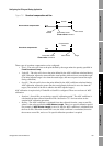
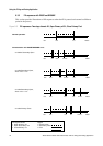
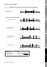
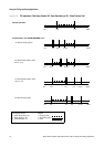
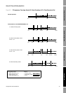
Figures 8-3 through 8-7 illustrate the various fill sequences for two-stage discrete filling or three-
position analog filling when the fill is paused and resumed at different points in the fill.
Note: The fill total is not held across a transmitter power cycle.
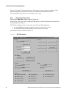
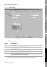
8.3.1 Using the Run Filler window
The ProLink II
Run Filler window is shown in Figure 8-1.
The Fill Setup, Fill Control, AOC Calibration, Fill Statistics, and Fill Data displays and controls are
listed and defined in Table 8-1.
The Fill Status fields show the current status of the fill or the filling application:
• A green LED indicates that the condition is inactive or the valve is closed.
• A red LED indicates that the condition is active or the valve is open.
The Fill Status fields are defined in Table 8-2.
Figure 8-1 Run Filler window