


6 Micro Motion
®
Model 1500 Transmitters with the Filling and Dosing Application
Connecting with ProLink II Software
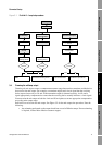
To access the configuration upload/download function:
1. Connect ProLink II to your transmitter as described in this chapter.
2. Open the
File menu.
• To save a configuration file to a PC, use the
Load from Xmtr to File option.
• To restore or load a configuration file to a transmitter, use the
Send to Xmtr from File
option.
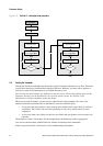
2.4 Connecting from a PC to a Model 1500 transmitter
ProLink II software can communicate with a Model 1500 transmitter using Modbus protocol on the
RS-485 physical layer. There are two connection types:
• RS-485 configurable connection
• SP (service port) non-configurable (standard) connection
Both connection types use the RS-485 terminals (terminals 33 and 34). These terminals are available
in service port mode for 10 seconds after transmitter power-up. After this interval, the terminals revert
to RS-485 mode.
• To make a service port connection, you must configure ProLink II appropriately and connect
during the 10-second interval after transmitter power-up. Once a service port connection is
made, the terminals will remain in service port mode. You may disconnect and reconnect as
often as required, as long as you continue to use service port mode.
• To make an RS-485 connection, you must configure ProLink II appropriately, wait for the
10-second interval to expire, then connect. The terminals will now remain in RS-485 mode,
and you may disconnect and reconnect as often as required, as long as you continue to use
RS-485 mode.
• To change from service port mode to RS-485 mode, or vice versa, you must cycle power to the
transmitter and reconnect using the desired connection type.
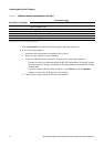
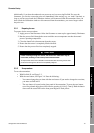
To connect a PC to the RS-485 terminals or an RS-485 network:
1. Attach the signal converter to the serial port of your PC, using a 25-pin to 9-pin adapter if
required.
2. To connect to the RS-485 terminals, connect the signal converter leads to terminals 33 and 34.
See Figure 2-1.
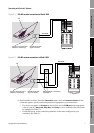
3. To connect to an RS-485 network, connect the signal converter leads to any point in the
network. See Figure 2-2.
4. For long-distance communication, or if noise from an external source interferes with the
signal, install 120-ohm, 1/2-watt resistors in parallel with the output at both ends of the
communication segment.
5. Ensure that the transmitter is disconnected from a host PLC.