


114 Micro Motion
®
Model 1500 Transmitters with the Filling and Dosing Application
Troubleshooting
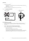
8. Test terminal pairs as follows:
a. Drive + against all other terminals except Drive –
b. Drive – against all other terminals except Drive +
c. Left pickoff + against all other terminals except Left pickoff –
d. Left pickoff – against all other terminals except Left pickoff +
e. Right pickoff + against all other terminals except Right pickoff –
f. Right pickoff – against all other terminals except Right pickoff +
g. RTD + against all other terminals except LLC + and RTD/LLC
h. LLC + against all other terminals except RTD + and RTD/LLC
i. RTD/LLC against all other terminals except LLC + and RTD +
Note: D600 sensors and CMF400 sensors with booster amplifiers have different terminal pairs.
Contact Micro Motion for assistance (see Section 1.8).
There should be infinite resistance for each pair. If there is any resistance at all, there is a short
between terminals. See Table 11-14 for possible causes and solutions.
9. If the problem is not resolved, contact Micro Motion (see Section 1.8).
To return to normal operation:
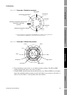
1. If you have a standard core processor:
a. Align the three guide pins on the bottom of the core processor with the corresponding
holes in the base of the core processor housing.
b. Carefully mount the core processor on the pins, taking care not to bend any pins.
2. If you have an enhanced core processor:
a. Plug the sensor cable onto the feedthrough pins, being careful not to bend or damage any
pins.
b. Replace the core processor in the housing.
3. Tighten the captive screw(s) to 6 to 8 in-lbs (0,7 to 0,9 N-m) of torque.
4. Replace the core processor lid.
Note: When reassembling the meter components, be sure to grease all O-rings.