


42 Micro Motion
®
Model 1500 Transmitters with the Filling and Dosing Application
Optional Transmitter Configuration
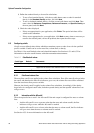
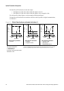
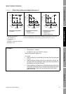
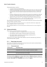
For the effect of flow direction on the mA output:
• See Figure 6-1 if the 4 mA value of the mA output is set to 0.
• See Figure 6-2 if the 4 mA value of the mA output is set to a negative value.
For a discussion of these figures, see the examples following the figures.
For the effect of flow direction on totalizers and flow values reported via digital communication,
see Table 6-3.
Figure 6-1 Effect of flow direction on mA outputs: 4mA value = 0
Reverse
flow
(1)
20
12
4
x0
20
12
4
-x x0
mA output configuration:
• 20 mA value = x
• 4 mA value = 0
To set the 4 mA and 20 mA values,
see Section 4.5.2.
Forward
flow
(2)
Zero flow
Reverse
flow
(1)
Forward
flow
(2)
Zero flow
Flow direction parameter:
•Forward
Flow direction parameter:
• Reverse
• Negate Forward
20
12
4
-x x0
Reverse
flow
(1)
Forward
flow
(2)
Zero flow
Flow direction parameter:
• Absolute value
• Bidirectional
• Negate Bidirectional
(1) Process fluid flowing in opposite direction from flow direction arrow on sensor.
(2) Process fluid flowing in same direction as flow direction arrow on sensor.
-x
mA output
mA output
mA output