


Configuration and Use Manual 11
Flowmeter Startup
Using ProLink II Required ConfigurationFlowmeter StartupBefore You Begin
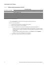
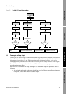
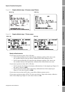
Figure 3-1 ProLink II – Loop test procedure
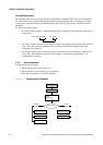
3.4 Trimming the milliamp output
Trimming the mA output creates a common measurement range between the transmitter and the device
that receives the mA output. For example, a transmitter might send a 4 mA signal that the receiving
device reports incorrectly as 3.8 mA. If the transmitter output is trimmed correctly, it will send a
signal appropriately compensated to ensure that the receiving device actually indicates a 4 mA signal.
You must trim the mA output at both the 4 mA and 20 mA points to ensure appropriate compensation
across the entire output range.
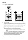
ProLink II is used to trim the mA output. See Figure 3-2 for the mA output trim procedure. Note the
following:
• Any trimming performed on the output should not exceed ± 200 microamps. If more trimming
is required, contact Micro Motion customer support.
Test
Fix Milliamp 1
ProLink Menu
Fix Discrete Out 1
Fix Discrete Out 2
Read Discrete Input
Enter mA value
Fix mA
ON or OFF
Read output at
receiving device
Verify state at
receiving device
Toggle remote input
device
Verify Present State LED
at transmitter
Correct? Correct? Correct?
Loop test successful
UnFix
Check output wiring
Troubleshoot receiving device
Loop test successful
Check input wiring
Troubleshoot input device
Yes No Yes No