


Configuration and Use Manual 113
Troubleshooting
Measurement Performance DefaultsTroubleshootingCompensation
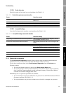
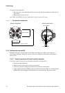
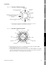
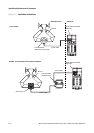
Figure 11-2 Sensor pins – Standard core processor
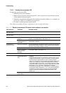
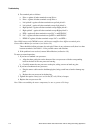
Figure 11-3 Sensor pins – Enhanced core processor
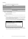
6. There should be no open circuits, i.e., no infinite resistance readings. The LPO and RPO
readings should be the same or very close (± 5 ohms).
7. Using the DMM, check between each pin and the sensor case. With the DMM set to its highest
range, there should be infinite resistance on each lead. If there is any resistance at all, there is a
short to case. See Table 11-14 for possible causes and solutions.
Left pickoff
( + )
Right pickoff
( + )
Drive
( + )
Drive
( – )
Right pickoff
( – )
Left pickoff
( – )
Lead length compensator
(1)
( + )
Resistance temperature detector return /
Lead length compensator
(common)
Resistance temperature detector
( + )
(1) LLC for all sensors except T-Series and CMF400 I.S. For T-Series sensors, functions as
composite RTD. For CMF400 I.S. sensors, functions as fixed resistor.
Left pickoff +
Right pickoff +
Drive + Drive –
Right pickoff –
Left pickoff –
LLC
RTD +
RTD –