


50 Micro Motion
®
Model 1500 Transmitters with the Filling and Dosing Application
Optional Transmitter Configuration
6.12.2 Changing the Modbus address
The transmitter’s Modbus address is used by devices on a network to identify and communicate with
the transmitter using Modbus protocol. The Modbus address must be unique on the network. If the
transmitter will not be accessed using Modbus protocol, the Modbus address is not required.
Modbus addresses must be in the range 1–110, inclusive.
If you are connected to the transmitter using an RS-485 connection, and you change the Modbus
address, then:
• If you are using ProLink II, ProLink II will automatically switch to the new address and retain
the connection.
• If you are using a different host program, the connection will be broken. You must reconnect
using the new Modbus address.
Note: Changing the Modbus address does not affect service port connections. Service port
connections always use a default address of 111.
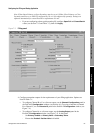
6.12.3 Changing the RS-485 parameters
RS-485 parameters control how the transmitter will communicate over its RS-485 terminals. The
following parameters can be set:
•Protocol
•Baud rate
• Parity
• Stop bits
To enable RS-485 communications with the transmitter from a remote device:
1. Set the transmitter’s digital communications parameters appropriately for your network.
2. Configure the remote device to use the specified parameters.
If you are connected to the transmitter using an RS-485 connection:
• And you change the the baud rate:
- If you are using ProLink II, ProLink II will automatically switch to the new baud rate and
retain the connection.
- If you are using a different host program, the connection will be broken. You must
reconnect using the new baud rate.
• And you change the protocol, parity or stop bits, all host programs will lose the connection.
You must reconnect using the new settings.
Note: Changing the RS-485 communication settings does not affect service port connections. Service
port connections always use default settings.
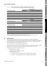
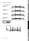
Not-A-Number (NAN) Process variables report IEEE NAN and Modbus scaled integers report Max Int.
Totalizers stop counting.
Flow to Zero Flow rates go to the value that represents zero flow; other process variables are not
affected. Totalizers stop counting.
None (default) Process variables reported as measured.
Table 6-6 Digital communications fault indicators and values continued
Fault indicator options Fault output value