


32 Micro Motion
®
Model 1500 Transmitters with the Filling and Dosing Application
Using the Transmitter
5.3 Viewing process variables
Process variables include measurements such as mass flow rate, volume flow rate, mass total, volume
total, temperature, and density.
To view process variables with ProLink II software:
1. The
Process Variables window opens automatically when you first connect to the transmitter.
2. If you have closed the
Process Variables window:
a. Open the
ProLink menu.
b. Select
Process Variables.
5.4 Viewing transmitter status and alarms
You can view transmitter status using the status LED or ProLink II.
The transmitter broadcasts alarms whenever a process variable exceeds its defined limits or the
transmitter detects a fault condition. Using ProLink II, you can view active alarms and you can view
the alarm log. For information regarding all the possible alarms, see Table 11-4.
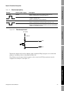
5.4.1 Using the status LED
The status LED is located on the front panel. This LED shows transmitter status as described in
Table 5-1.
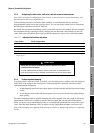
5.4.2 Using ProLink II software
To view current status and alarms with ProLink II software:
1. Click
ProLink.
2. Select
Status. The status indicators are divided into three categories: Critical, Informational,
and Operational. To view the indicators in a category, click on the tab.
• A tab is red if one or more status indicators in that category is on.
• Within the tabs, current status alarms are shown by red status indicators.
Table 5-1 Transmitter status reported by the status LED
Status LED state Alarm priority Definition
Green No alarm Normal operating mode
Flashing yellow No alarm Zero in progress
Yellow Low severity alarm • Alarm condition: will not cause measurement error
• Outputs continue to report process data
• This alarm may indicate “Fill not ready” condition,
e.g., target set to 0, no flow source configured, no
valves configured.
Red High severity (critical fault) alarm • Alarm condition: will cause measurement error
• Outputs go to configured fault indicators