


Configuration and Use Manual 25
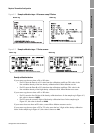
Required Transmitter Configuration
Using ProLink II Required ConfigurationFlowmeter StartupBefore You Begin Using ProLink II Required ConfigurationFlowmeter StartupBefore You Begin Using ProLink II Required ConfigurationFlowmeter StartupBefore You Begin Using ProLink II Required ConfigurationFlowmeter StartupBefore You Begin
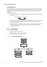
4.5.4 Configuring the fault action, fault value, and last measured value timeout
Note: If the mA output is configured for valve control, it cannot be used to report alarm status, and
the mA output will never go to fault levels.
If the transmitter encounters an internal fault condition, it can indicate the fault by sending a
preprogrammed output level to the receiving device. You can specify the output level by configuring
the fault action. Options are shown in Table 4-8.
By default, the transmitter immediately reports a fault when a fault is encountered. You can configure
the transmitter to delay reporting a fault by changing the last measured value timeout to a non-zero
value. During the fault timeout period, the transmitter continues to report its last valid measurement.
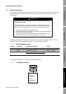
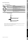
4.5.5 Configuring added damping
A damping value is a period of time, in seconds, over which the process variable value will change to
reflect 63% of the change in the actual process. Damping helps the transmitter smooth out small,
rapid measurement fluctuations:
• A high damping value makes the output appear to be smoother because the output must change
slowly.
• A low damping value makes the output appear to be more erratic because the output changes
more quickly.
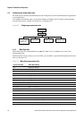
The added damping parameter specifies damping that will be applied to the mA output. It affects the
measurement of the process variable assigned to the mA output, but does not affect other outputs.
When you specify a new added damping value, it is automatically rounded down to the nearest valid
value. Note that added damping values are affected by the Update Rate parameter (see Section 6.7).
Note: Added damping is not applied if the mA output is fixed (i.e., during loop testing) or is reporting
a fault.
Table 4-8 mA output fault actions and values
Fault action Fault output value
Upscale 21–24 mA (default: 22 mA)
Downscale 1.0–3.6 mA (default: 2.0 mA)
Internal zero The value associated with 0 (zero) flow, as determined by URV and LRV values
None
(1)
(1) If the mA output fault action is set to None, the digital communications fault action should also be set to None. See
Section 6.12.1.
Tracks data for the assigned process variable; no fault action
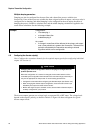
CAUTION
Setting the fault action to NONE may result in process error due to
undetected fault conditions.
To avoid undetected fault conditions when the fault action is set to NONE, use
some other mechanism such as digital communications to monitor device status.