


122 Micro Motion
®
Model 1500 Transmitters with the Filling and Dosing Application
Installation Architectures and Components
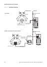
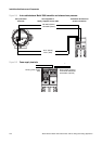
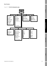
Figure B-4 4-wire cable between Model 1500 transmitter and enhanced core processor
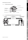
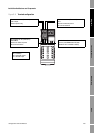
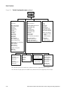
Figure B-5 Power supply terminals
Core processor
terminals
Transmitter terminals for
sensor connection
VDC+ (Red)
VDC– (Black)
RS-485/B (Green)
RS-485/A (White)
User-supplied or
factory-supplied 4-wire cable
–
+ –
+
Power supply jumper to
other Model 1500/2500
transmitters (optional)
Primary power supply
(DC)