


Configuration and Use Manual 15
Using ProLink II Required ConfigurationFlowmeter StartupBefore You Begin
Chapter 4
Required Transmitter Configuration
4.1 Overview
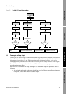
This chapter describes the configuration procedures that are usually required when a transmitter is
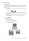
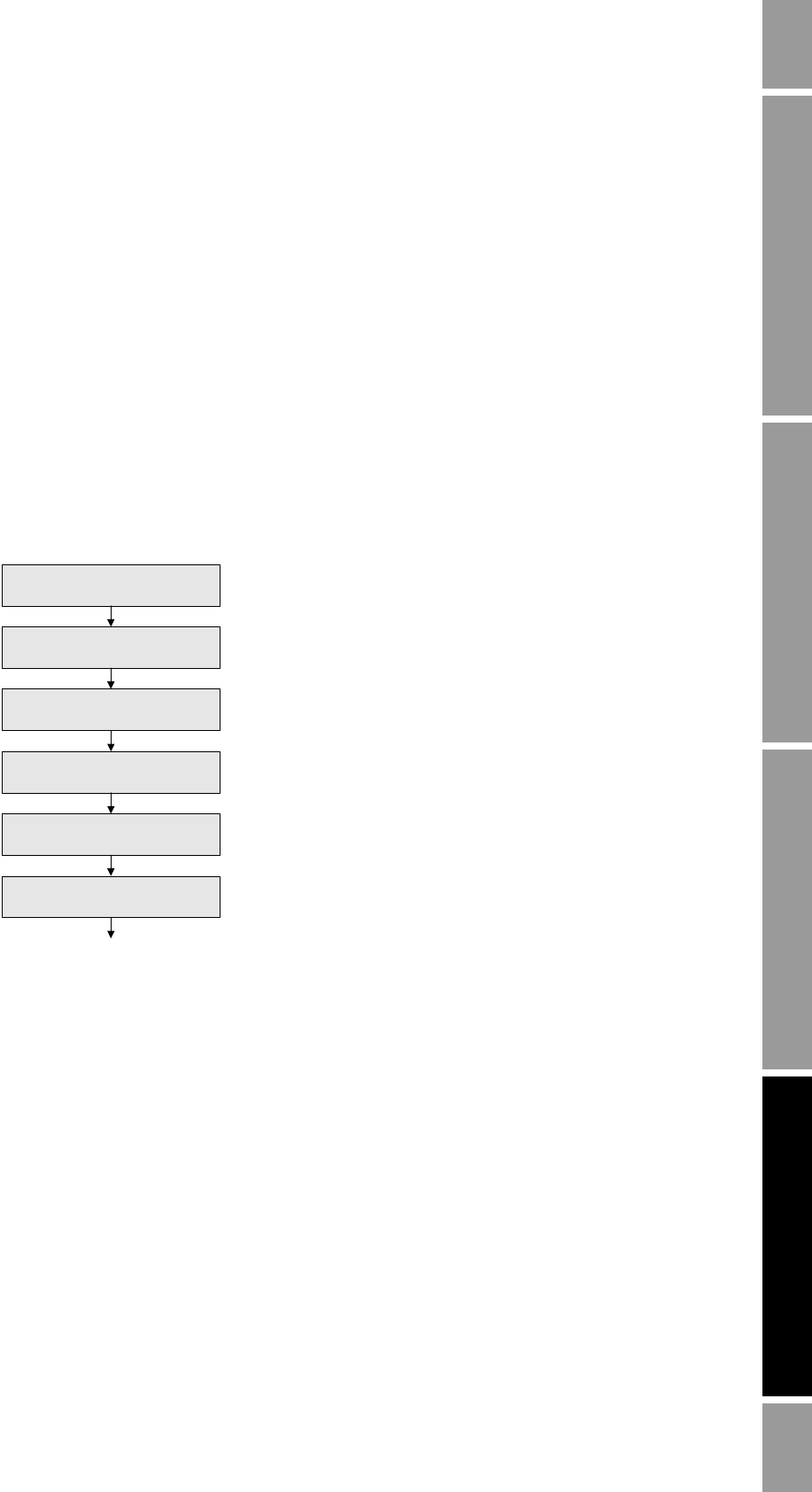
installed for the first time. The procedures in this chapter should be performed in the order shown in
Figure 4-1.
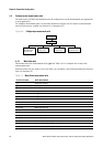
Figure 4-1 Required configuration procedures in order
This chapter provides basic flowcharts for each procedure. For more detailed flowcharts, see the
ProLink II flowcharts, provided in Appendix C.
Default values and ranges for the parameters described in this chapter are provided in Appendix A.
For optional transmitter configuration parameters and procedures, see Chapter 6. For configuration of
the filling and dosing application, see Chapter 7.
Note: All ProLink II procedures provided in this chapter assume that your computer is already
connected to the transmitter and you have established communication. All ProLink II procedures also
assume that you are complying with all applicable safety requirements. See Chapter 2 for more
information.
Characterize the flowmeter
(Section 4.2)
Configure the channels
(Section 4.3)
Configure measurement units
(Section 4.4)
Configure mA output
(Section 4.5)
Configure discrete outputs
(1)
(Section 4.6)
Configure discrete input
(1)
(Section 4.7)
Done
(2)
(1) Only the input or outputs that have been assigned to
a channel need to be configured.
(2) If the meter verification option has been purchased,
the final configuration step should be to establish a
meter verification baseline (see Section 4.8).