


108 Micro Motion
®
Model 1500 Transmitters with the Filling and Dosing Application
Troubleshooting
11.24.1 Checking the core processor LED
To check the core processor LED:
1. Maintain power to the transmitter.
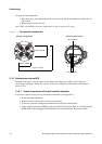
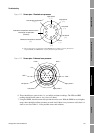
2. Remove the core processor lid (see Figure B-2). The core processor is instrinsically safe and
can be opened in all environments.
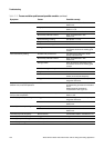
3. Check the core processor LED against the conditions described in Table 11-11 (standard core
processor) or Table 11-12 (enhanced core processor).
4. To return to normal operation, replace the lid.
Note: When reassembling the meter components, be sure to grease all O-rings.
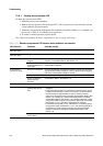
Table 11-11 Standard core processor LED behavior, meter conditions, and remedies
LED behavior Condition Possible remedy
1 flash per second (ON
25%, OFF 75%)
Normal operation No action required.
1 flash per second (ON
75%, OFF 25%)
Slug flow See Section 11.17.
Solid ON Zero or calibration in
progress
If calibration is in progress, no action required. If no calibration is in
progress, contact Micro Motion. See Section 1.8.
Core processor
receiving between 11.5
and 5 volts
Check power supply to transmitter. See Section 11.14.1, and refer to
Appendix B for diagrams.
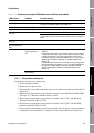
3 rapid flashes,
followed by pause
Sensor not recognized Check wiring between transmitter and sensor (remote core processor
with remote transmitter installation). Refer to Appendix B for diagrams,
and see your transmitter installation manual.
Improper configuration Check sensor characterization parameters. See Section 4.2.
Broken pin between
sensor and core
processor
Contact Micro Motion. See Section 1.8.
4 flashes per second Fault condition Check alarm status.
OFF Core processor
receiving less than 5
volts
• Verify power supply wiring to core processor
. Refer to Appendix B for
diagrams.
• If transmitter status LED is lit, transmitter is receiving power. Check
voltage across terminals 1 (VDC+) and 2 (VDC–) in core processor.
Normal reading is approximately 14 VDC. If reading is normal,
internal core processor failure is possible. Contact Micro Motion. See
Section 1.8. If reading is 0, internal transmitter failure is possible.
Contact Micro Motion. See Section 1.8. If reading is less than 1 VDC,
verify power supply wiring to core processor. Wires may be switched.
See Section 11.14.1, and refer to Appendix B for diagrams.
• If transmitter status LED is not lit, transmitter is not receiving power.
Check power supply. See Section 11.14.1, and refer to Appendix B
for diagrams. If power supply is operational, internal transmitter,
display, or LED failure is possible. Contact Micro Motion. See
Section 1.8.
Core processor
internal failure
Contact Micro Motion. See Section 1.8.