


Configuration and Use Manual 111
Troubleshooting
Measurement Performance DefaultsTroubleshootingCompensation
5. There should be no open circuits, i.e., no infinite resistance readings. The LPO and RPO
readings should be the same or very close (± 5 Ω). If there are any unusual readings, repeat the
coil resistance tests at the sensor junction box to eliminate the possibility of faulty cable. The
readings for each coil pair should match at both ends.
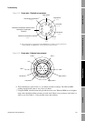
6. Leave the core processor terminal blocks disconnected. At the sensor, remove the lid of the
junction box and test each sensor terminal for a short to case by placing one DMM lead on the
terminal and the other lead on the sensor case. With the DMM set to its highest range, there
should be infinite resistance on each lead. If there is any resistance at all, there is a short to
case.
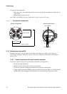
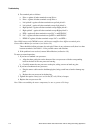
7. At the sensor, test terminal pairs as follows:
a. Brown against all other terminals except Red
b. Red against all other terminals except Brown
c. Green against all other terminals except White
d. White against all other terminals except Green
e. Blue against all other terminals except Gray
f. Gray against all other terminals except Blue
g. Orange against all other terminals except Yellow and Violet
h. Yellow against all other terminals except Orange and Violet
i. Violet against all other terminals except Yellow and Orange
Note: D600 sensors and CMF400 sensors with booster amplifiers have different terminal pairs.
Contact Micro Motion for assistance (see Section 1.8).
There should be infinite resistance for each pair. If there is any resistance at all, there is a short
between terminals.
8. See Table 11-14 for possible causes and solutions.
9. If the problem is not resolved, contact Micro Motion (see Section 1.8).
10. To return to normal operation:
a. Plug the terminal blocks into the terminal board.
b. Replace the end-cap on the core processor housing.
c. Replace the lid on the sensor junction box.
Note: When reassembling the meter components, be sure to grease all O-rings.
Table 11-13 Coils and test terminal pairs
Coil
Test terminal pair
Colors Numbers
Drive coil Brown to red 3 — 4
Left pickoff coil (LPO) Green to white 5 — 6
Right pickoff coil (RPO) Blue to gray 7 — 8
Resistance temperature detector (RTD) Yellow to violet 1 — 2
Lead length compensator (LLC) (all sensors except CMF400 I.S. and T-Series)
Composite RTD (T-Series sensors only)
Fixed resistor (CMF400 I.S. sensors only)
Yellow to orange 1 — 9