


94 Micro Motion
®
Model 1500 Transmitters with the Filling and Dosing Application
Troubleshooting
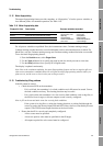
11.9 Transmitter status LED
The Model 1500 transmitter includes a LED that indicates transmitter status. See Table 11-3. If the
status LED indicates an alarm condition:
1. View the alarm code using ProLink II.
2. Identify the alarm (see Section 11.10).
3. Correct the condition.
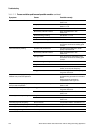
mA reading correct at low
currents but wrong at higher
currents
mA loop resistance may be too high Verify that mA output load resistance is below
maximum supported load (see installation
manual for your transmitter).
Cannot zero with Zero
button
Not pressing Zero button for sufficient
interval
Button must be pressed for 0.5 seconds to be
recognized. Press button until LED starts to
flash yellow, then release button.
Core processor in fault mode Correct core processor faults and retry.
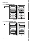
Cannot connect to terminals
33 & 34 in service port mode
Terminals not in service port mode Terminals are accessible in service port mode
ONLY for a 10-second interval after power-up.
Cycle power and connect during this interval.
Leads reversed. Switch leads and try again.
Transmitter installed on multidrop
network
All Model 1500 and 2500 devices on network
default to address=111 during 10-second
service port interval. Disconnect or power down
other devices, or use RS-485 communications.
Cannot establish Modbus
communication on terminals
33 & 34
Incorrect Modbus configuration After 10-second interval on power-up, the
transmitter switches to Modbus
communications. Default settings are:
• Address=1
• Baud rate=9600
• Parity=odd
Verify configuration. Default settings can be
changed using ProLink II v2.0 or higher.
Leads reversed Switch leads and try again.
DI is fixed and does not
respond to input switch
Possible internal/external power
configuration error
Internal means that the transmitter will supply
power to the output. External means that an
external pull-up resistor and source are
required. Verify configuration setting is correct
for desired application.
Table 11-3 Model 1500/2500 transmitter status reported by the status LED
Status LED state Alarm priority Definition
Green No alarm Normal operating mode
Flashing yellow No alarm Zero in progress
Yellow Low severity alarm • Alarm condition: will not cause measurement error
• Outputs continue to report process data
• May indicate that the fill is not completely
configured
Red High severity alarm • Alarm condition: will cause measurement error
• Outputs go to configured fault indicators, unless
the output is configured for valve control
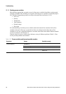
Table 11-2 I/O problems and remedies continued
Symptom Possible cause Possible remedy