


28 Micro Motion
®
Model 1500 Transmitters with the Filling and Dosing Application
Required Transmitter Configuration
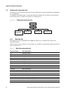
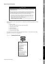
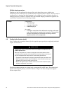
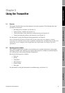
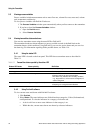
To configure the discrete output, see the menu flowchart in Figure 4-9.
Figure 4-9 Configuring the discrete output(s)
WARNING
Upon transmitter startup or abnormal power reset, any external device
controlled by a discrete output may be momentarily activated.
Upon transmitter startup or abnormal power reset, discrete output states are
unknown. As a result, an external device controlled by a discrete output may
receive current for a brief period.
When using Channel B as a discrete output:
• You can prevent current flow upon normal startup by setting Channel B polarity
to active low.
• There is no programmatic method to prevent current flow for Channel B upon
abnormal power reset. You must design the system so that a brief current flow to
the external device controlled by Channel B cannot cause negative
consequences.
When using Channel C as a discrete output, there is no programmatic method to
prevent current flow upon either transmitter startup or abnormal power reset. You
must design the system so that a brief current flow to the external device controlled
by Channel C cannot cause negative consequences.
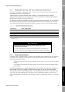
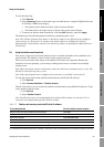
Table 4-10 Discrete output assignments and output levels
Assignment Condition Discrete output level
(1)
(1) Voltage descriptions in this column assume that Polarity is set to Active High. If Polarity is set to Active Low, the voltages
are reversed.
Primary valve (DO1 only)
Secondary valve (DO2 only)
Open Site-specific
Closed 0 V
Fill in progress (DO2 only) ON Site-specific
OFF 0 V
Fault indication (DO2 only) ON Site-specific
OFF 0 V
Configuration
ProLink Menu
Discrete IO
Discrete output
· DO1 assignment
· DO1 polarity
· DO2 assignment
· DO2 polarity
Discrete input
· DI assignment