


Configuration and Use Manual 105
Troubleshooting
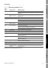
Measurement Performance DefaultsTroubleshootingCompensation
11.21 Checking the characterization
A transmitter that is incorrectly characterized for its sensor might produce inaccurate output values. If
the flowmeter appears to be operating correctly but sends inaccurate output values, an incorrect
characterization could be the cause.
If you discover that any of the characterization data are wrong, perform a complete characterization.
See Section 4.2.
11.22 Checking the calibration
Improper calibration can cause the transmitter to send unexpected output values. If the transmitter
appears to be operating correctly but sends inaccurate output values, an improper calibration may be
the cause.
Micro Motion calibrates every transmitter at the factory. Therefore, you should suspect improper
calibration only if the transmitter has been calibrated after it was shipped from the factory.
The calibration procedures in this manual are designed for calibration to a regulatory standard. See
Chapter 10. To calibrate for true accuracy, always use a measurement source that is more accurate
than the meter. Contact Micro Motion customer service for assistance.
Note: Micro Motion recommends using meter factors, rather than calibration, to prove the meter
against a regulatory standard or to correct measurement error. Contact Micro Motion before
calibrating your flowmeter. For information on meter performance, see Chapter 10.
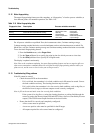
11.23 Checking the test points
Some status alarms that indicate a sensor failure or overrange condition can be caused by problems
other than a failed sensor. You can diagnose sensor failure or overrange status alarms by checking the
meter test points. The test points include left and right pickoff voltages, drive gain, and tube
frequency. These values describe the current operation of the sensor.
11.23.1 Obtaining the test points
To obtain the test points with ProLink II software:
1. Select
Diagnostic Information from the ProLink menu.
2. Write down the values you find in the
Tube Frequency box, the Left Pickoff box, the Right
Pickoff
box, and the Drive Gain box.
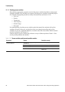
11.23.2 Evaluating the test points
Use the following guidelines to evaluate the test points:
• If the drive gain is unstable, refer to Section 11.23.3.
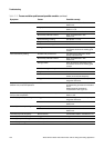
• If the value for the left or right pickoff does not equal the appropriate value from Table 11-7,
based on the sensor flow tube frequency, refer to Section 11.23.5.
• If the values for the left and right pickoffs equal the appropriate values from Table 11-7, based
on the sensor flow tube frequency, record your troubleshooting data and contact Micro Motion
customer service. See Section 1.8.