


26 Micro Motion
®
Model 1500 Transmitters with the Filling and Dosing Application
Required Transmitter Configuration
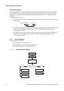
Multiple damping parameters
Damping can also be configured for the mass flow and volume flow process variables (see
Section 6.6). If one of these process variables has been assigned to the mA output, a non-zero value is
configured for its damping, and added damping is also configured for the mA output, the effect of
damping the process variable is calculated first, and the added damping calculation is applied to the
result of that calculation. See the following example.
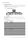
4.6 Configuring the discrete output(s)
Note: Configure the transmitter channels for the required output types before configuring individual
outputs. See Section 4.3.
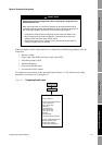
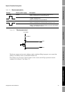
The discrete outputs generate two voltage levels to represent ON or OFF states. The voltage levels
depend on the output’s polarity, as shown in Table 4-9
. Figure 4-8 shows a diagram of a typical
discrete output circuit.
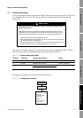
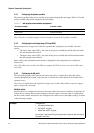
Example
Configuration:
• Flow damping: 1
• mA output: Mass flow
• Added damping: 2
As a result:
• A change in mass flow will be reflected in the primary mA output
over a time period that is greater than 3 seconds. The exact time
period is calculated by the transmitter according to internal
algorithms which are not configurable.
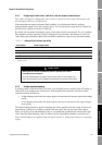
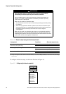
CAUTION
Changing the channel configuration without verifying I/O configuration can
produce process error.
When the configuration of a channel is changed, the channel’s behavior will be
controlled by the configuration that is stored for the new channel type, which may or
may not be appropriate for the process. To avoid causing process error:
• Configure the channels before configuring the discrete output (see Section 4.3
).
• When changing the discrete output configuration, be sure that all control loops
affected by this output are under manual control.
• Before returning the loop to automatic control, ensure that the discrete output is
correctly configured for your process.