


Configuration and Use Manual 119
Transmitter Menus IndexNE53 HistoryDiagrams
Appendix B
Installation Architectures and Components
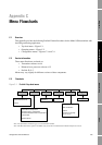
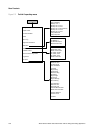
B.1 Overview
This appendix provides illustrations of different flowmeter installation architectures and components,
for the Model 1500 transmitter with the filling and dosing application.
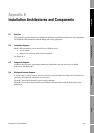
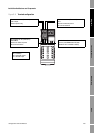
B.2 Installation diagrams
Model 1500 transmitters can be installed in two different ways:
• 4-wire remote
• Remote core processor with remote transmitter
See Figure B-1.
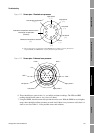
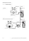
B.3 Component diagrams
In remote core processor with remote transmitter installations, the core processor is installed
stand-alone. See Figure B-2.
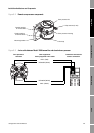
B.4 Wiring and terminal diagrams
A 4-wire cable is used to connect the core processor to the transmitter. See Figure B-3 (standard core
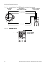
processor) or Figure B-4 (enhanced core processor).
Figure B-5 shows the transmitter’s power supply terminals.
Figure B-6 shows the output terminals for the Model 1500 transmitter with the filling and dosing
application.