


Configuration and Use Manual 93
Troubleshooting
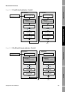
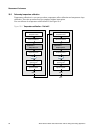
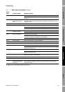
Measurement Performance DefaultsTroubleshootingCompensation
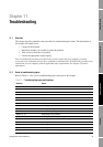
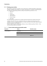
Some fault conditions can be corrected by cycling power to the transmitter. A power cycle can clear
the following:
• Loop test
• Zero failure
• Stopped internal totalizer
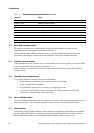
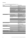
11.8 I/O problems
If you are experiencing problems with an mA output, discrete output, or discrete input, use Table 11-2
to identify an appropriate remedy.
Table 11-2 I/O problems and remedies
Symptom Possible cause Possible remedy
No output
Loop test failed
Power supply problem Check power supply and power supply wiring.
See Section 11.14.1.
Fault condition present if fault
indicators are set to downscale or
internal zero
Check the fault indicator settings to verify
whether or not the transmitter is in a fault
condition. See Section 4.5.4 to check the mA
fault indicator.
If a fault condition is present, see Section 11.7.
Channel not configured for desired
output (Channel B or C only)
Verify channel configuration for associated
output terminals.
mA output < 4 mA Process condition below LRV Verify process.
Change the LRV. See Section 4.5.2.
Fault condition if fault indicator is set to
internal zero
Check the fault indicator settings to verify
whether or not the transmitter is in a fault
condition. See Section 4.5.4.
If a fault condition is present, see Section 11.7.
Open in wiring Verify all connections.
Channel not configured for mA
operation
Verify channel configuration.
Bad mA receiving device Check the mA receiving device or try another
mA receiving device. See Section 11.16.
Bad output circuit Measure DC voltage across output to verify that
output is active.
Constant mA output Output is fixed in a test mode Exit output from test mode. See Section 3.3.
Zero calibration failure Cycle power.
Stop flow and rezero. See Section 3.5.
mA output consistently out of
range
Fault condition if fault indicator is set to
upscale or downscale
Check the fault indicator settings to verify
whether or not the transmitter is in a fault
condition. See Section 4.5.4.
If a fault condition is present, see Section 11.7.
LRV and URV not set correctly Check the LRV and URV. See Section 11.20.
Consistently incorrect mA
measurement
Output not trimmed correctly Trim the output. See Section 3.4.
Incorrect flow measurement unit
configured
Verify flow measurement unit configuration. See
Section 11.19.
Incorrect process variable configured Verify process variable assigned to mA output.
See Section 4.5.1.
LRV and URV not set correctly Check the LRV and URV. See Section 11.20.