


Configuration and Use Manual 51
Optional Transmitter Configuration
Optional Configuration Using the FillerFiller ConfigurationUsing the Transmitter
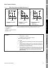
6.12.4 Changing the floating-point byte order
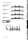
Four bytes are used to transmit floating-point values. For contents of bytes, see Table 6-7.
The default byte order for the transmitter is 3–4–1–2. You may need to reset byte order to match the
byte order used by a remote host or PLC. Byte order codes are listed in Table 6-8.
6.12.5 Changing the additional communications response delay
Some hosts or PLCs operate at slower speeds than the transmitter. In order to synchronize
communication with these devices, you can configure an additional time delay to be added to each
response the transmitter sends to the remote host.
The basic unit of delay is in terms of 2/3 of one character time as calculated for the current serial port
baud rate setting and character transmission parameters. This basic delay unit is multiplied by the
configured value to arrive at the total additional time delay. You can specify a value in the range 1 to
255.
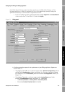
6.13 Configuring variable mapping
The Variable Mapping panel in the Configuration window provides another way to assign the primary
variable (PV). The PV parameter shown on this panel is the same as the Primary Variable parameter
in the Analog Output panel (see Section 4.5): if you change the parameter here, it is automatically
changed in the Analog Output panel, and vice versa.
The secondary variable (SV), tertiary variable (TV), and quaternary variable (QV) are not used by the
Model 1500 transmitter with the filling and dosing application, and cannot be changed.
Table 6-7 Byte contents in Modbus commands and responses
Byte Bits Definitions
1 S E E E E E E E S = Sign
E = Exponent
2 E M M M M M M M E = Exponent
M = Mantissa
3 M M M M M M M M M = Mantissa
4 M M M M M M M M M = Mantissa
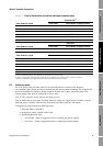
Table 6-8 Byte order codes and byte orders
Byte order code Byte order
01–2–3–4
13
–4–1–2
22–1–4–3
34–3–2–1