


Configuration and Use Manual 27
Required Transmitter Configuration
Using ProLink II Required ConfigurationFlowmeter StartupBefore You Begin Using ProLink II Required ConfigurationFlowmeter StartupBefore You Begin Using ProLink II Required ConfigurationFlowmeter StartupBefore You Begin Using ProLink II Required ConfigurationFlowmeter StartupBefore You Begin
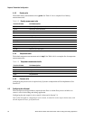
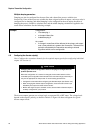
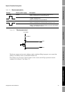
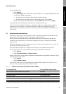
Figure 4-8 Discrete output circuit
The discrete outputs can be used to indicate a fault, to indicate filling in progress, or to control the
primary or secondary valves, as described in Table 4-10.
Note: Before you can assign a discrete output to valve control, the Fill Type parameter must be
configured. See Chapter 7 and Figure 7-3.
Table 4-9 Discrete output polarity
Polarity Output power supply Description
Active high Internal • When asserted, the circuit provides a pull-up to 15 V.
• When not asserted, the circuit provides 0 V.
External • When asserted, the circuit provides a pull-up to a site-specific
voltage, maximum 30 V.
• When not asserted, circuit provides 0 V.
Active low Internal • When asserted, the circuit provides 0 V.
• When not asserted, the circuit provides a pull-up to 15 V.
External • When asserted, the circuit provides 0 V.
• When not asserted, the circuit provides a pull-up to a site-specific
voltage, to a maximum of 30 V.
15 V (Nom)
Out+
Out–
3.2 Kohm