


Configuration and Use Manual 23
Required Transmitter Configuration
Using ProLink II Required ConfigurationFlowmeter StartupBefore You Begin Using ProLink II Required ConfigurationFlowmeter StartupBefore You Begin Using ProLink II Required ConfigurationFlowmeter StartupBefore You Begin Using ProLink II Required ConfigurationFlowmeter StartupBefore You Begin
If the mA output is used to report mass flow or volume flow, the following parameters must be
configured:
• Primary variable
• Upper range value (URV) and lower range value (LRV)
• AO (analog output) cutoff
• AO added damping
• Fault action and fault value
• Last measured value timeout
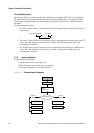
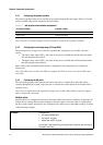
To configure the mA output, see the menu flowchart in Figure 4-7. For details on mA output
parameters, see Sections 4.5.1 through 4.5.5.
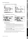
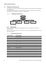
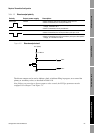
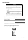
Figure 4-7 Configuring the mA output
CAUTION
Changing the channel configuration without verifying I/O configuration can
produce process error.
When the configuration of a channel is changed, the channel’s behavior will be
controlled by the configuration that is stored for the new channel type, which may or
may not be appropriate for the process. To avoid causing process error:
• Configure the channels before configuring the mA output (see Section 4.3
).
• When changing the mA output configuration, be sure that all control loops
affected by this output are under manual control.
• Before returning the loop to automatic control, ensure that the mA output is
correctly configured for your process.
Configuration
ProLink Menu
Analog output
Primary variable is
Process variable measurement
· Lower range value
· Upper range value
· AO cutoff
· AO added damp
· Lower sensor limit
· Upper sensor limit
·Min span
· AO fault action
· Last measured value timeout
Process variable measurement
· Enable 3 position valve
· Analog valve setpoint
· Analog valve closed value