


Configuration and Use Manual 43
Optional Transmitter Configuration
Optional Configuration Using the FillerFiller ConfigurationUsing the Transmitter
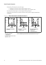
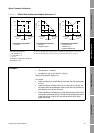
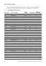
Figure 6-2 Effect of flow direction on mA outputs: 4mA value < 0
Example 1
Configuration:
• Flow direction = Forward
• mA output: 4 mA = 0 g/s; 20 mA = 100 g/s
(See the first graph in Figure 6-1.)
As a result:
• Under conditions of reverse flow or zero flow, the mA output level
is 4 mA.
• Under conditions of forward flow, up to a flow rate of 100 g/s, the
mA output level varies between 4 mA and 20 mA in proportion to
(the absolute value of) the flow rate.
• Under conditions of forward flow, if (the absolute value of) the flow
rate equals or exceeds 100 g/s, the mA output will be proportional
to the flow rate up to 20.5 mA, and will be level at 20.5 mA at
higher flow rates.
Reverse
flow
(1)
mA output
20
12
4
–x x0
20
12
–x x0
mA output configuration:
• 20 mA value = x
• 4 mA value = –x
• –x < 0
To set the 4 mA and 20 mA values,
see Section 4.5.2.
Forward
flow
(2)
Zero flow
Reverse
flow
(1)
Forward
flow
(2)
Zero flow
Flow direction parameter:
•Forward
Flow direction parameter:
• Reverse
• Negate Forward
20
12
4
–x x0
Reverse
flow
(1)
Forward
flow
(2)
Zero flow
Flow direction parameter:
• Absolute value
• Bidirectional
• Negate Bidirectional
(1) Process fluid flowing in opposite direction from flow direction arrow on sensor.
(2) Process fluid flowing in same direction as flow direction arrow on sensor.
mA output
mA output
4