


Chapter1—Welcome to the world of the AW4416
26 — Operation Guide
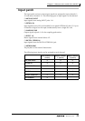
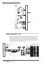
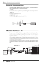
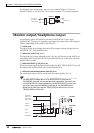
Recorder input patching
This section assigns the signals that are input to tracks 1–16 of the recorder sec-
tion. The following types of signal can be selected.
❍ STEREO
The stereo bus output signal that has passed through the stereo output channel.
❍ BUS 1–8
The output signal of buses 1–8.
❍ DIRECT OUT 1–16
The direct output signal of input channels 1–16.
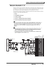
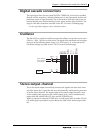
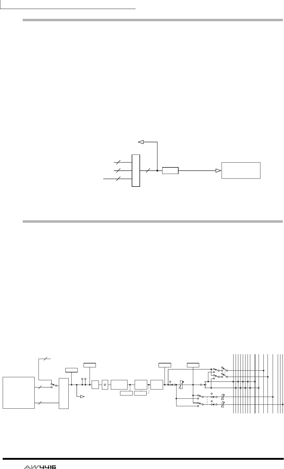
Monitor channels 1–16
These are monaural channels that are assigned to the track 1–16 outputs of the
recorder section. According to the input monitor settings or the state of the trans-
port, they will input either the signals being input to tracks 1–16, or the playback
signals of tracks 1–16.
As an exception, the stereo track will be patched to monitor channels 1/2 when
the stereo track of that song is being played back, and the remainder of the moni-
tor channels 3–16 will be muted.
The structure of these channels is the same as that of the input channels, with the
exception that the direct output is fixed at a point immediately before the attenu-
ator.
RECORDER
INPUT 1(...16)
INPUT PATCH
BUS 1~8
CH DIRECT OUT1~16
STEREO
RECORDER INPUT 1~16
DITHER
8
16 16
2
RECORDER
RECORDER MONI 1(...16)
Mono in X 16
INPUT PATCH
ON LEVEL
PA N
PRE/POST ON AUX
16
16
2
RECORDER INPUT 1-16
INPUT
MONITOR
RECORDER
DIRECT OUT
RECORDER
REPRO1-16
RECORDER
ST Trk L/R
INSERT
METER
METER
(FL Display)
AT T
BUS1
BUS2
BUS3
BUS4
BUS5
BUS6
BUS7
BUS8
STEREO L
STEREO R
SOLO L
SOLO R
AUX 1
AUX 6
AUX 7(EFF1)
AUX 8(EFF2)
METER METER
PREFADER LISTEN/
AFTER PAN
SOLO
METERMETER
4 BAND EQ
INPUT
DELAY
DY-
NAMICS
(EQ) (Gain Reduction)
...